Chapter 2 Installation and Connection
FC300
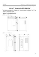
Outline dimensions of FC300 series inverters:
Installation dimension
Inverter Model
W(mm) H(mm) D(mm)
FC300-0.75-S2
FC300-1.5-S2
FC300-0.75-T4 108
152
130
FC300-1.5-T4
FC300-2.2-T4
FC300-2.2-S2
FC300-3.0-S2
FC300-3.7-S2
FC300-5.5-S2
140
205
156
FC300-3.0-T4
FC300-3.7-T4
FC300-5.5-T4
FC300-7.5-S2
FC300-7.5-T4
170
280
184
FC300-9-S2
FC300-11-T4
210
338
200
FC300-15-T4
FC300-11-S2
FC300-18.5-T4
248
375
228
Outline dimension
W1(mm) H1(mm)
D(mm)
94
139
4
125
191
5
110
266
6
192
319
7
160
356
8
2.2 Installation Guidelines
Because inverter is one kind of precise power electronic products, the working environment
directly influences the performance and service life of inverter. Therefore, please follow the
below:
1. Check whether the inverter installation position environment comply with 1.2.3
instructions, if not, please DO NOT install it, otherwise it will cause damage to inverter.
2. Inverter adopts plastic parts, please do not exert a big force on the cover plate. Install
carefully in case of any damage.
3. If conditions allow please openly install the backside plate and cooling fins out of control
cabinet, to effectively decrease the temperature in the electrical control cabinet.
4. Install inverter in clean place if possible, or inside of the enclosed type shield board which
prevents all the floating material.
5. Inverter shall be installed in vertical direction solidly on the installation board with screws.
6. Pay attention to the heat dissipation method of the inverter which is installed in a control
cabinet: under the condition that there are two or more inverters and ventilation fan are
8

