Page 18 of 42
Shenzhen Reader Technology Co., Ltd
6 Examples of Driver Interface for Step-servo Motor
6.1 Overview
The input signal end of step-servo motor driver employs the light-coupled isolation
technology. For the step-by-step impulse signal, some isolate the side OC diode from
cutoff to conduction (e.g. the valid falling edge of pulse signal inputted from the diode
minus end) and some do so from conduction to cutoff (e.g. the valid rising edge of pulse
signal inputted from the diode minus end). When it is indicated whether the pulse signal of
motor driver is the valid rising edge or the valid falling edge, it will be subject to the pulse
signal inputted from the minus end of side OC diode.
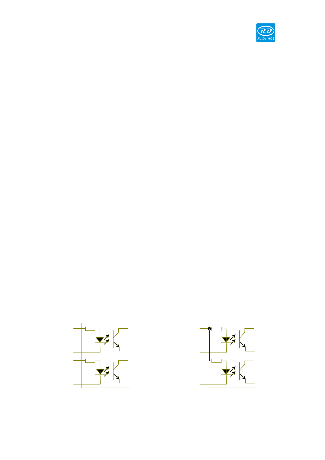
Some input signals of motor driver are independent and some are internally of
common anode, so some have 4 external leading-out wires and some 3 wires (only the
pulse and directional signals are counted) as shown in Figure 10 and 11. Meanwhile, the
input signal can generally be compatible with different voltage classes. If it is higher than
the 5V signal, it is necessary to connect the current-limiting resistance externally. The
interface signals of motor driver for RD mainboard are the 5V signals that should directly
be abutted with the corresponding terminals to the driver.
The interface pulse end of each motor driver for RD mainboard can provide such two
signals as the rising-edge walk and falling-edge travel. The improper use of the pulse-end
signal may give rise to the lost steps, even back-run and finally dislocation of processed
figure when the motor steers. In addition, this mainboard provide two directional signals
not restrict in requirements. Either signal can be connected with the directional signal end
of driver in the common-anode mode. Both directional signal ends can also be connected
with the driver in the differential mode. In such a case, plus and minus can be exchanged
at random. The result of exchange is that the rotating direction of motor is different from
the actually desired direction. At this time the polarity of directional signal for the motor
can be modified on the PC software. In this section is exampled the driver of step-servo
motor popular in the market. In addition to that the correct wiring scheme of this
mainboard and motor driver is provided, it is recommended to use the common-anode
connection in all wiring schemes.
PU+
+5V
PU-
PU
DR+
DR-
Figure: 6.1-1 Four Inputs, Independent
Input Signal of Driver
DR
Figure: 6.1-2 Three Inputs, Common-anode
Input Signal of Driver
18

