- You are here:
- AM.CO.ZA Buythis CNC Utilities Homepage
- RDZ01 LFS MANUALV1.10 .pdf
- Page 27 of 28
RDZ01 LFS Manual
NOTICE:
Limit input can be enabled or disabled. When limit is disabled, the laser head will neglects the status of the limits.
The laser head will not be protected.
The above wiring diagram means the limit switch is valid when it closed with OGND. So in the RD_Tracer,
the polarity of the limits must be set to be negative.
Low level will trigger protection is default.
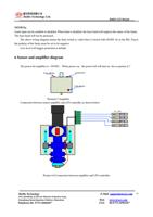
6 Sensor and amplifier diagram
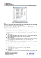
The power for amplifier is +24VDC,When power on,the power led will turn on. See as picture 6-7
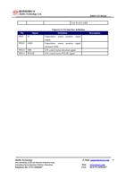
Picture6-7 Amplifier
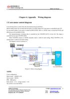
Connection between sensor amplifier and LFS controller as shown below:
屏蔽层
红(red)
黑(black)
棕(brown)
白(white)
黄yellow)
To LFS
ePLC-CN0 PIN23OVCC
ePLC-CN0 PIN24 OGND
ePLC-CN3 PIN1 AN1
ePLC-CN0 PIN3 IN3
Picture 6-8 Connection between amplifier and LFS controller
RuiDa Technology
1B-1,Building 5,Tian'an Nanyou Industry Area,
Dengliang Road,Nanshan District, Shenzhen
Telephone:86- 0755-26066687
E-Mail: support@rd-acs.com 27
Web: www.rd-acs.com
FAX: 86-0755-26982287


