- You are here:
- AM.CO.ZA Buythis CNC Utilities Homepage
- RDZ01 LFS MANUALV1.10 .pdf
- Page 23 of 28
RDZ01 LFS Manual
2 auxiliary gas control diagram
Auxiliary gas control has two methods. One of them is need two output of LFS to control two relays. Another
is one output to control one relay. The methods can be select in the RD_Tracer.
Method 1:
Compressed air and O2 are controlled independently by its own solenoid valve, air outlet of solenoid valve
connect a three way joint, and then connect to the air inlet of laser head.
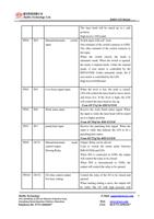
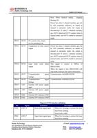
When auto/manual switch is set to manual mode, it is for non-metal cutting mode, CON0-PIN10 (OUT2)
output high level, the relay is opened, O2 control valve closed. Then CON0-PIN13 (OUT5) output low level. The
connected relay is closed, compressed air output to three ways joint. Compressed air blows into the laser head for
non-metal cutting.
When automatic/manual switch is set to automatic mode, it is for metal cutting mode, CON0-PIN13 (OUT5)
output high level, the relay is opened, compressed air control valve closed. Then CON0-PIN10 (OUT2) output
low level. The connected relay is closed, O2 output to three ways joint. O2 blows into the laser head for non-metal
cutting.
RuiDa Technology
1B-1,Building 5,Tian'an Nanyou Industry Area,
Dengliang Road,Nanshan District, Shenzhen
Telephone:86- 0755-26066687
E-Mail: support@rd-acs.com 23
Web: www.rd-acs.com
FAX: 86-0755-26982287


