- You are here:
- AM.CO.ZA Buythis CNC Utilities Homepage
- RDZ01 LFS MANUALV1.10 .pdf
- Page 8 of 28
RDZ01 LFS Manual
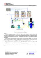
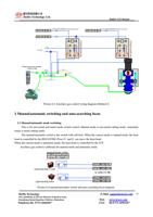
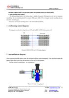
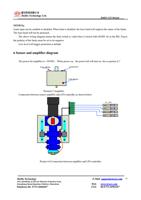
PIN4 IN4
Manual/automatic
input
switch
The laser head will be raised up to a safe
position.
High level (+24V)valid
Switch input with self –lock.
One terminal of the switch connects to GND.
The other terminal of the switch connects to
the input.
When the switch closed, the mode is
automatic mode. When the switch is opened,
the mode is manual mode. Under the manual
mode, Z axis motor is controlled by the
RDC633XM. Under automatic mode, the Z
axis motor is controlled by the LFS.
High level (GND)valid
PIN5
PIN6
PIN7
PIN9
IN5
IN6
IN7
OUT1
Live focus signal input
Work status input
punch hole input
Manual/automatic
control output.
Driving Relay.
mode
When the level is low, the node is closed.
LFS will control the laser head to move down
and focus live. If the level is high, the LFS
will control the laser head to rise up.
From OUT1of the RDC633XM
Receive the work finish status signal. When
the input is valid, the laser head will be raised
up to a higher position
From OUT0of the RDC633XM
Receive the punching hole signal. When the
input is valid, that indicate the LFS to be a
punching hole status.
From OUT2of the RDC633XM
Output. Relay can be drived.
Used to switch the motor pulse between
RDC633XM and LFS.
When IN4 is connected to GND, the output
will control the relay to be closed.
When IN4 is disconnected to GND, the
output will control the relay to be opened
PIN10 OUT2 O2 relay control output
For laser cutting
Control the relay of the O2 to be closed and
opened.
When starting cutting a curve, the output will
be valid. The O2 with high pressure will
RuiDa Technology
1B-1,Building 5,Tian'an Nanyou Industry Area,
Dengliang Road,Nanshan District, Shenzhen
Telephone:86- 0755-26066687
E-Mail: support@rd-acs.com 8
Web: www.rd-acs.com
FAX: 86-0755-26982287


