LFS-PM-T43 operating manual
XIX
PIN4
Out1
General output
—
PIN5
Out2
General output
—
PIN6
Out3
General output
—
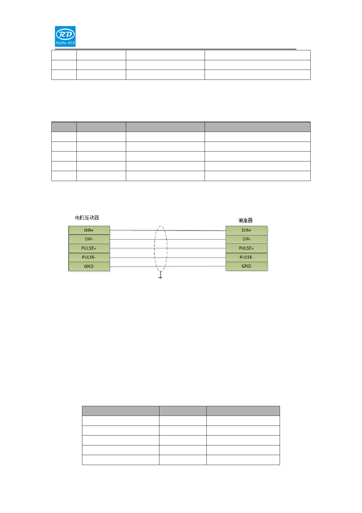
1.1.17 CN8 motor control interface for step mode
PIN
SIGNAL
DEFINITION
DESCRIPTION
PIN1
Pulse-
—
—
PIN2
Pulse+
—
—
PIN3
Dir-
—
—
PIN4
Dir+
—
—
PIN5
GND
GND
—
1) To control step motor, differential mode and common-anode mode can be applied. We
recommend user to select differential mode .
2) To control servo motor, please set the parameters correctly according to the operation
manual of the servo drive。
Set the servo drive to work at the position mode.
The polarity of the pulse and direction.
The number of pulse/per round
1.1.18 MOTOR control interface for servo mode
PIN(color of wire)
PIN1(yellow)
PIN2(blue)
PIN3(black)
PIN4(orange)
PIN5(red)
signal
SPEED
OS
A+
B+
Z+
definition
+/-10V speed command
Zero speed
Encoder A+
Encoder B+
Encoder Z+

