LFS-PM-T43 operating manual
XVII
conduction with the machine. Or the capacity sensor will not work normally.
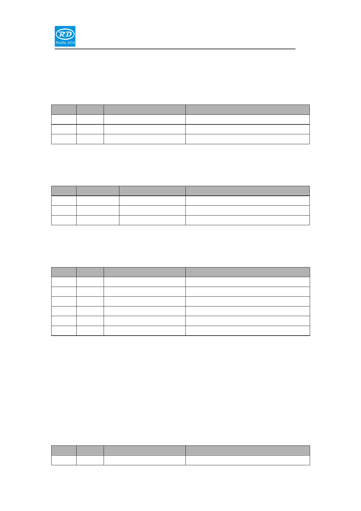
1.1.10 CN1 ----RS232
PIN
PIN 1
PIN 2
PIN 3
SIGNAL
TXD
RXD
GND
DEFINITION
send data
Receive data
GND
1.1.11 CN2----analog interface
DESCRIPTION
—
—
—
PIN
SIGNAL
PIN1
AGND
PIN2
Analog In
PIN3 Analog Out
DEFINITION
Analog GND
Analog input
Analog output
DESCRIPTION
Input scale:0—10V
Output scale:0—10V
1.1.12 CN3----general input and output
PIN SIGNAL
DEFINITION
DESCRIPTION
PIN1 Lmt+
PIN2 Lmt-
UP limit
Down limit
24V level
24V level
PIN3 EmStp
Emergency input
Low level valid
PIN4
In1
General input
—
PIN5
In2
General input
—
PIN6
In3
General input
—
Limit switch include of up limit and down limit in the Z axis. support N.C
and N.O mode. If the limit is N.O, the polarity should be set to be negative.
If the limit is N.C, the polarity should be set to be positive.
The limit switch can be mechanical, opto-electric and magic type. But all
the limit should be 24V standard. It can be OC interface mode.
1.1.13 CN4 control input
PIN SIGNAL
PIN1 Trace
DEFINITION
随动控制信号输入
DESCRIPTION
低电平时,处于随动下降并跟随,高电平

