



Home
3D
PrintUP 3D Printer
PioCreat 3D Printer
Printers
FastCOLOUR >>
ATools
DTF Textile
UV-DTF
FlatPRINT
PrintExp
InkRIP
Lasers
TruCUT CO
2
>>
TruCUT RDWorks
TruCUT 2020+
TruCUT Express
TruCUT Lite >>
4030 & Vertical Software
4030 & Vertical Documents
New 6040 Desktop
LabelMark
RayCUT
MorCUT >>
MorCUT-Cyclops
LaserMaster
Plasmas
MetalWise
Fabricam
Routers
EasyRoute
PowerRoute
Blade Cutters
Vinyl Cutters >>
V-Series
V-Smart
V-Auto (& V-Smart+)
Vinyl4
Flatbed Cutters >>
FlatCUT
Label Cutters >>
V-Auto Label Cutters
Software >>
VinylCut
More
FastCUT
Heatware
Rollman
ScreenMaster
Other Software
Miscellaneous
AM.CO.ZA
/
Buy CNC Software
/
CNC Software Training
/
CNC Software Downloads
Sales: 072 222 2211
Support: 076 666 6655
Training: 060 818 1818
Jo’burg: 087 802 5368
Cape Town: 087 802 7106
An
Project
Multimedia
Univision Videos
#SortIT Videos
MakersLab.TV
Software Training
Welldone Gallery
Updates
Prevision Blog
Cornerstone Trust
Email Campaigns
Contact Us
Sales WhatsApp
060 600 6000
Support WhatsApp
060 600 7000
Johannesburg Headquarters
011 397 1429
087 802 5368
Cape Town Showroom
021 555 3250
087 802 7106
Links
CNC Machine Repair
Vinyl Cutter
Heatware
You are here:
AM.CO.ZA
Buythis
CNC Utilities Homepage
TruCUT-CO2-Laser-Machine
TruCUT-PRO Metal Laser 2016+ Model Software
LFS-PM-T43operating manual.pdf
Page 13 of 35
LF
S
-PM-T43 oper
a
n
g manual
I
LF
S
-PM-T43 aut
oma
c dis
t
ance
c
on
tr
oller
oper
a
ng manual
V1.0
R
ead this
manual be
f
or
e oper
a
o
n
T
he
c
on
t
en
t
include
of
electric
c
onnec
o
ns
and
oper
a
ng s
t
ep
s
R
ead
the
manual
t
o
ensur
e
electric
c
onnec
o
n
R
uiDa T
echnology C
o
., Lt
d
Addr:
1TH
FL
OOR
,5TH
BUI
LDING,NANY
OU
TIANAN
INDUS
TRIAL Z
ONE,SHENZHEN
T
el:
0755--26066687
F
a
x
:
0755--26982287
E
-mail:
sales@r
d-acs.c
om
W
eb: w
w
w
.r
d-acs.c
om
LF
S
-PM-T43 oper
a
n
g manual
II
COPY RIGHT
RuiDa technology keep the right of the following:
1.
Ruida
technology
owns
all
the
patent
right
and
property
right
of
the
products.
Ruida
will
preserve
the
right
to
pursue
legal
actions
against
copying
,
producing
this product.
2.
Ruida
have
the
right
to
modify
the
content
of
the
manual
and
reserved
the
right
to
modify the related
document
of the product.
3.
User
should
read
the
manual
carefully
.
Ruida
have
no
duty
to
be
responsible
for
the
direct,
indirect
and
incidental
loss
because
of
the
faulty
operations
of
the
users.
Operation
does not follow the manual
Operation does
not follow the related standards.
4.
During
the
motion,
it
is
dangerous
because
of
the
laser
and
mechanical
motion.
U
ser should ensure the safety
.
LF
S
-PM-T43 oper
a
n
g manual
III
C
ontents
LF
S
-PM-T43 oper
a
n
g manual
IV
CHAP
TER 1 INTR
ODUC
TION
1
1.1
PR
ODUC
T I
NTR
ODUC
TION
1
CHAP
TER 2 FUNC
TI
ON
2
2.1
T
OUCH SCREEN
2
2.2
FUNC
TI
ONS
3
2.2.1
MAI
N ME
NU
3
2.2.2
P
ARAMETER SE
T
TI
NG
3
2.2.3
P
ARAMETER MANA
GEMENT
5
2.2.4
ALARM INF
ORMA
TI
ON
6
2.2.5
CAP
A
CITY CALIBRA
TION
6
2.2.6
A
UX
I
LI
AR
Y C
ONTR
OL
7
2.2.7
S
Y
S
TEM INF
ORMA
TION
8
2.2.8
S
Y
S
TEM TI
ME
8
CHAP
TER 3 E
LE
C
TRIC C
ONNE
C
TIONS
10
3.1
INTERF
A
CE OF TH
E C
ONTR
OLLER
10
3.1.1
Sensor
I
NTERF
A
CE
11
3.1.2
CN1
11
3.1.3
CN2
11
3.1.4
CN3
11
3.1.5
CN4
12
3.1.6
CN5
12
3.1.7
CN6
12
3.1.8
CN7
13
3.1.9
CN8
13
3.1.10
MO
T
OR
13
3.1.11
HMI
14
3.1.12
USB
14
3.1.13
LAN
14
3.2
LED INDI
C
A
T
OR
15
CHAP
TER 4 TE
S
T
16
4.1
TUNI
NG
16
4.2
CUT
TING TE
S
T
17
CHAP
TER 5 ALARM INF
ORMA
TION
21
5.1
INTR
ODUC
TION OF THE ALARM
21
5.1.1
S
Y
S
TEM F
A
UL
T
21
5.1.2
LI
MIT TRIGGER
21
5.1.3
RE
SET F
A
UL
T
21
LF
S
-PM-T43 oper
a
n
g manual
V
5.1.4
CAP
A
CITY F
A
UL
T
22
5.1.5
CRASH ALARM
22
5.1.6
EMER
GNE
CY S
T
OP
22
5.1.7
F
OLL
O
WI
NG ERR
OR
22
5.1.8
MUL
TI
-ERR
OR
23
CHAP
TER 6 ASSEMBLING
24
6.1
SI
ZE OF TH
E C
ONTR
OLLER
24
6.2
SI
ZE OF TH
E AMPLI
FIER
24
APPENDIX
TR
OUBLE SHOO
T
25
LF
S
-PM-T43 oper
a
n
g manual
VI
Chap
t
er
1 In
tr
oducon
1.1
Pr
oduct in
tr
oduco
n
LFS-PM-T43
is
a
automatic
distance
control
system
that
based
on
the
capacity
sensor
.
This
system
ha
s
a
4.3”
TFT
touch
screen
and
can
display
the
work
status
and
detecting
capacity
value.
A
n
advanced
capacity
detecting
technology
has
been
applied
to
have
a
stable
and
anti-interference
capacity
result.
W
ith
this
sensor
detecting
technology
,
the
responsibility
and
accuracy
have
been
improved.
T
he
key
functions are just like following:
1)
Control
servo or step motors, high responsibility and accuracy
。
2)
S
upport crash
alarm,
limit trigger protection and servo alarm protection.
3)
A
utomatic calibration and can compatible with the third party
’
s laser head.
4)
S
upport
focus
distance
modified
on
line.
capacitor
detecting
scale
is
0~9.9mm.
5)
W
ork status of the laser head indicates and alarm indicates.
6)
S
upport dif
ferent setting of the rising height.
R
ising speed can be modified.
7)
A
uxiliary gas control.
S
upport 3 channels auxiliary gas control
。
8)
F
irmware updated by U disk
。
LF
S
-PM-T43 oper
a
n
g manual
VII
Chap
t
er 2 Funcons
1.2
4.3
”
t
ouch scr
een
This
dist
ance
controller
is
included
of
a
4.3”
touch
TFT
screen.
The
resolution
is
480X272.
the
laser
head
work
status
is
displayed
in
the
monit
or
and
param
eters
can
be
modified
with
the
monitor
.
t
he
display
area
is
function
button
area,
data
display
area,
running
status
display
area
and
alarm
display
area.
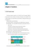
T
he main interface is just as the following:
F
unction butt
on area
:
touch the buttons can enter dif
ferent function control menu.
Data di
splay
:
here is used to display the det
ecting value of the capacitor sensor and
other set
values
。
F
ocus position
:
the distance between the nozzle and the work pi
ece.
A
ctual position
:
the actual val
ue of the capacitor detected.
F
ollowing error
:
the error between the focus position and the actual
position.
C
apacitor value
:
the value that the control
ler has detect from the capaci
ty sensor
;
Running
status
:
display
the status of the laser head.
A
larm display
:
alarm status display
.
I
f there are
several
alarm triggered at the same
time, user can touch t
he
“
alarm info
”
to check the alarm information in detail.
M
ain in
t
erf
ace
The communication between the the controller and t
he touch screen monitor is by RS232.
LF
S
-PM-T43 oper
a
n
g manual
VIII
If
all
the
electrical
connections
has
been
done
correct
ly
,
when
power
on
the
controller
,
t
he
monitor
of
the
controller
will
go
to
the
main
i
nterface.
If
there
are
no
error
happened,
that
means
the automatic distance control
ler work well.
But
i
f
the
m
onitor
indicate
that
connection
failed
because
of
the
cable
fault
or
other
reasons
,
”
connection
failed”
will
be
popped
up.
User
shoul
d
check
the
cable
and
the
sensor
devices.
1.3
Contr
ol functions
1.1.1
M
ain interface intr
oduction
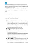
“tracing on/off”
:
E
nable or disable the t
racing function.
I
f it is tracing on, the color of
the
button
wil
l
changed
into
green,
which
means
the
cont
roller
is
under
the
tracing
status.
I
f
the
height
of
work
sheet
changes,
the
laser
head
will
tracing
the
movement
of
the
work
sheet
and
always
keep
the
distance
to
be
a
constant
value.
I
f
it
is
tracing
of
f,
the
traci
ng
functi
on
is
disabled.
I
f
the
height
of
the
work
piece
changes,
the
laser
head
has no response to that during t
he motion of the cutting system.
“
fast/slow
”
:
is used to switch the manual speed to faster or slow
.
。
“menu”
:
there are
children
menus in the menu to set some functions.
“reset”
:
T
o reset the di
stance controller
. Before running reset function, be sure that
the upper limit has been installed correctly
.
NOTICE:
T
here
is
danger
during
the
reset
operation
because
of
the
mechanical
motion.
S
o all the section should be checked before that and try to avoid of human harm.
“±0.1”
:
modify
the
dist
ance
between
the
nozzle
and
the
work
sheet.
P
ress
one
time, 0.1m
m will increase or decrease
。
“move up
、
move down”
:
to control the laser head to move up or move down.
I
f the
button is pressed, the laser head will be always moving until the button is released.
“alarm
info”
:
Press
the
button;
user
will
go
to
the
alarm
informat
ion
records
interface.
U
ser
can
check
the
alarm
information
that
happened
recently
.
T
he
maximum
LF
S
-PM-T43 oper
a
n
g manual
IX
number of t
he alarm record is 9.
“Function”
:
go
to
the
auxiliary
gas
test
and
capacitor
calibration
menu
“system info”
:
check the version of the controller and multi-language
selection
.
“system time”
:
modify the system time
。
1.1.2
P
ar
ame
t
er se
ng
Press
“
menu
”
to
enter
the
interface
of
craft
parameter
setting,
height
parameter
setting,
velocity parameter setting, machine parameter setting and other parameters.
N
otice
:
Before
operating
the
distance
control
ler
,
be
sure
that
the
parameters
has
already
set
correctly
.
The sense of the par
ame
t
er
s is sho
w
n
as the t
able
:
C
on
tr
ol
PID lt
er
I
ncrease
the
value
w
i
ll
improve
the
responsibility
of
t
he
laser head.
Alarm
m
e
F
ilter
time
for
crash
alarm
protect
ion.
I
f
the
value
i
s
too
small,
the
crash
alarm
will
usual
ly
triggered
because
of
the
metal
dross
during
cutting.
I
f
the
value
i
s
too
big,
this
wil
l
decrease the responsibility of the crash alarm
protection
.
Gas
dela
y
A
uxiliary gas rel
ease time before cutting or piercing.
P
ier
ce g
as
A
uxiliary gas selection for piercing.
LF
S
-PM-T43 oper
a
n
g manual
X
Cu
n
g
g
as
A
uxiliary gas selection for cutti
ng
。
H
eigh
t
R
ise posi
T
he rising height for laser head duri
ng jump motion
。
Alarm posi
W
hen
the
alarm
tri
ggered,
the
laser
head
is
on
the
stop
height
S
t
db
y posi
W
hen
the
cutting
task
is
finished,
the
laser
head
is
on
the
positi
on.
F
ocus posi
T
he
distance
between the nozzle and the work piece
R
ese
t posi
W
hen
reset
the
laser
head,
the
laser
head
will
t
rigger
the
limit switch and move reversely for this distance
F
ollo
w err
or
D
uring
a
close
control,
the
error
between
the
actual
posit
ion
and
referenced
poison
should
never
beyond
the
value.
I
f
that
happened
,
system
protection
will
be
execut
ed
and
generate
the alarm
of following error over limit
SPEED
R
ising spd
R
ising speed
T
r
acing spd
T
he maximum tracing speed
。
R
ese
t spd
L
aser head reset speed
f
as
t
T
he manual fast speed
slo
w
T
he manual slow speed
machine
polarity
S
et the rotation of the motor
acc
M
otion acceleration
。
S
cr
e
w pit
ch
S
crew pitch
r
esoluon
W
hen the motor rotate one round, the number of control pulse
should sent to the m
otor drive
O
ther
par
ame
t
er
s
R
ese
t En
E
nable or disable the reset when power on
C
r
ash En
I
f
the
crash
alarm
is
enabl
ed,
when
the
laser
head
has
touched
the
work
piece
for
a
certai
n
time(over
the
filt
er
ti
me),
system
will
rise
up
the
laser
head
and
stop
the
motion
of
t
he
cutting
system
I
f it is disabled, the crash alarm will be neglected.
Lm
t SNS
S
et
the
sense
of
the
limit
switch.
I
f
a
NPN
l
imit
switch
i
s
installed,
user
should
set
the
polarity
to
be
negat
ive
.
I
f
it
is
"
Do you need help?
Call Me Back