Page 28 of 63
6.1 Overview
RDC6432G control system user manual V1.1
The input signal end of the stepper motor driver adopts optocoupler isolation technology. For
stepping pulse signals, some of the isolation side optocoupler diodes from cut-off to conduction
(that is, the falling edge of the pulse signal input from the negative end of the diode is valid) , And
some are the isolation side optocoupler diode from on to off (that is, the rising edge of the pulse
signal input from the negative end of the diode is valid).
When the pulse signal of the motor driver is valid at the rising edge or the falling edge, the
pulse signal input from the negative terminal of the photocoupler diode on the isolation side
shall prevail.
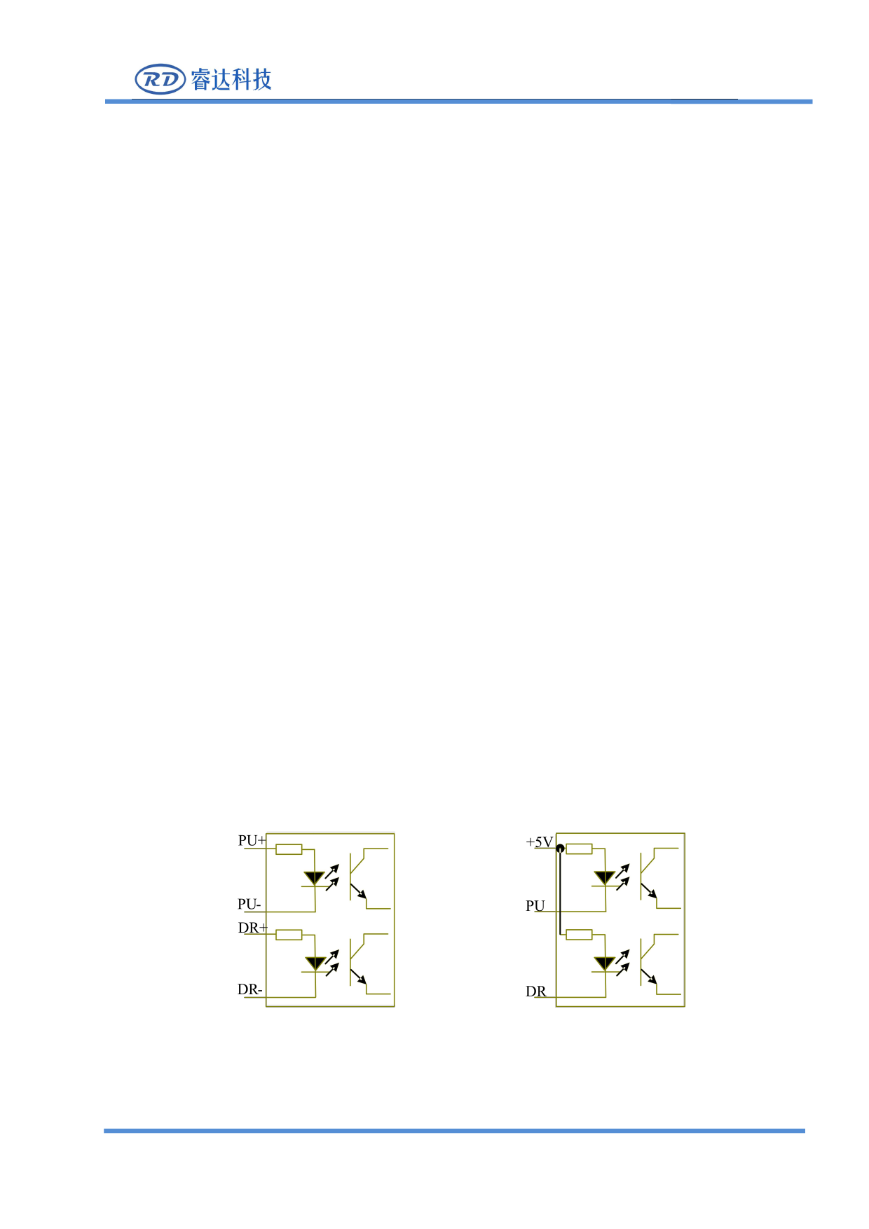
Some of the motor driver input signals are independent, and some are internal common anodes,
so some of the outgoing lead wires are 4, and some are 3 (only counting pulse and direction
signals), as shown in Figure 6.1-1 and Figure 6.1-2 .
Each motor driver interface of RDC6432G mainrboard provides a direction signal, a pulse signal,
and a 5V signal for common anode connection. The pulse signal and direction signal are both OC
output.
RDC6432G only supports common anode connection, and cannot use common cathode or
differential connection. Among them, the polarity of the direction signal can be set by the PC,
and whether the pulse signal is valid at the rising edge or the falling edge can also be set by the
PC.
Figure 6.1-1 Four inputs, independent
drive input signal
Figure 6.1-2 Three inputs, drive input signal
common anode
SHENZHEN RUIDA TECHNOLOGY
21

