LFS-PM-T43 operating manual
PIN6(green)
PIN7(green/white)
PIN8(brown)
PIN9(yellow/white)
PIN10(blue/white)
PIN11(black/white)
PIN12(orange/white)
PIN13(red/white)
PIN14(purple)
PIN15(brown/white)
XX
SON
CLR
+24V
AGND
GND
A-
B-
Z-
ALM
GND
Servo on
Alarm clear
+24V output
Analog GND
GND
Encoder A-
Encoder B-
Encoder Z-
Servo alarm input
GND
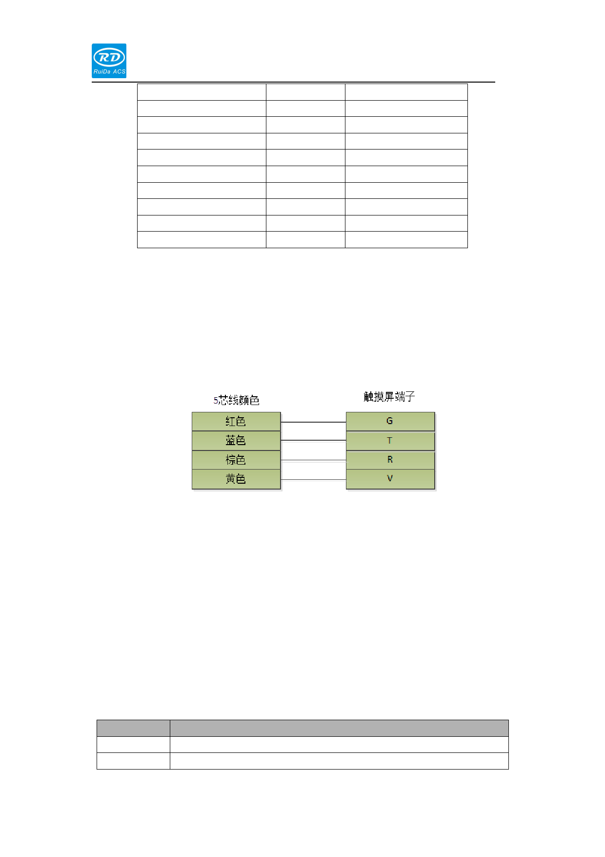
1.1.19HMI
The connection between the distance controller and the displayer is shown
as follows:
1.1.20 USB
USB is a U disk interface that used to upgrade the firmware.
LAN is a ETHERNET interface.
1.5 Led Indicator
LED name
+24V
Run
24V Power indicator
System running indicator
Description


