
Page 40 of 48
Wuhan Raycus Fiber Laser Technologies Co., Ltd.
User Guide of Raycus CW fiber laser
Press the “Laser” button (enable hardware emission) on the front panel;
PIN 7-9 of the DB25 control interface is applied to 24V (enable hardware
emission);
Send the start or stop emitting command (enable hardware emission) to control the
emission by the PC software;
9) The laser is controlled by the user's "modulation" signal provided by the external MOD
interface
See 4.8 to get the process of laser shutting down.
4.7.4 AD mode
When PIN 7-9 of the DB25 control interface is applied to 24V, the laser enters the external
AD mode, and the power of the laser is controlled by the voltage obtained by PIN 22-25 of the
DB25 interface connector (1V-10% power, 10V-100% power).
When PIN 7-9 of the DB25 control interface is applied to 0V or left floating, the power of
the laser is set by serial port or Ethernet.
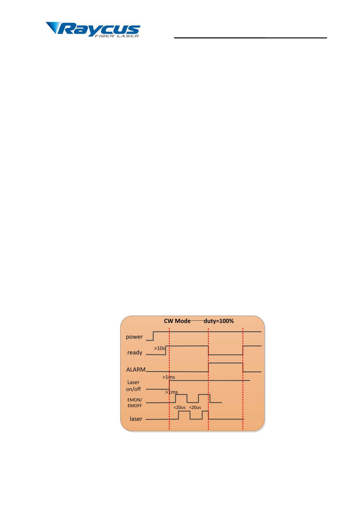
4.7.5 Control sequence diagram
Figure 27 Control sequence diagram of CW mode
25
 Raycus Continuous Wave Fiber Laser User Guide, C1500S & C2000S")
 Raycus Continuous Wave Fiber Laser User Guide, C1500S & C2000S")
 Raycus Continuous Wave Fiber Laser User Guide, C1500S & C2000S")
 Raycus Continuous Wave Fiber Laser User Guide, C1500S & C2000S")
 Raycus Continuous Wave Fiber Laser User Guide, C1500S & C2000S")
 Raycus Continuous Wave Fiber Laser User Guide, C1500S & C2000S")
 Raycus Continuous Wave Fiber Laser User Guide, C1500S & C2000S")
 Raycus Continuous Wave Fiber Laser User Guide, C1500S & C2000S")
 Raycus Continuous Wave Fiber Laser User Guide, C1500S & C2000S")