
BWT20 Qilin double swing handheld laser
2.11 Lasweelrdincgosnysttremoluseirnmtaenurafl aVc1.e0
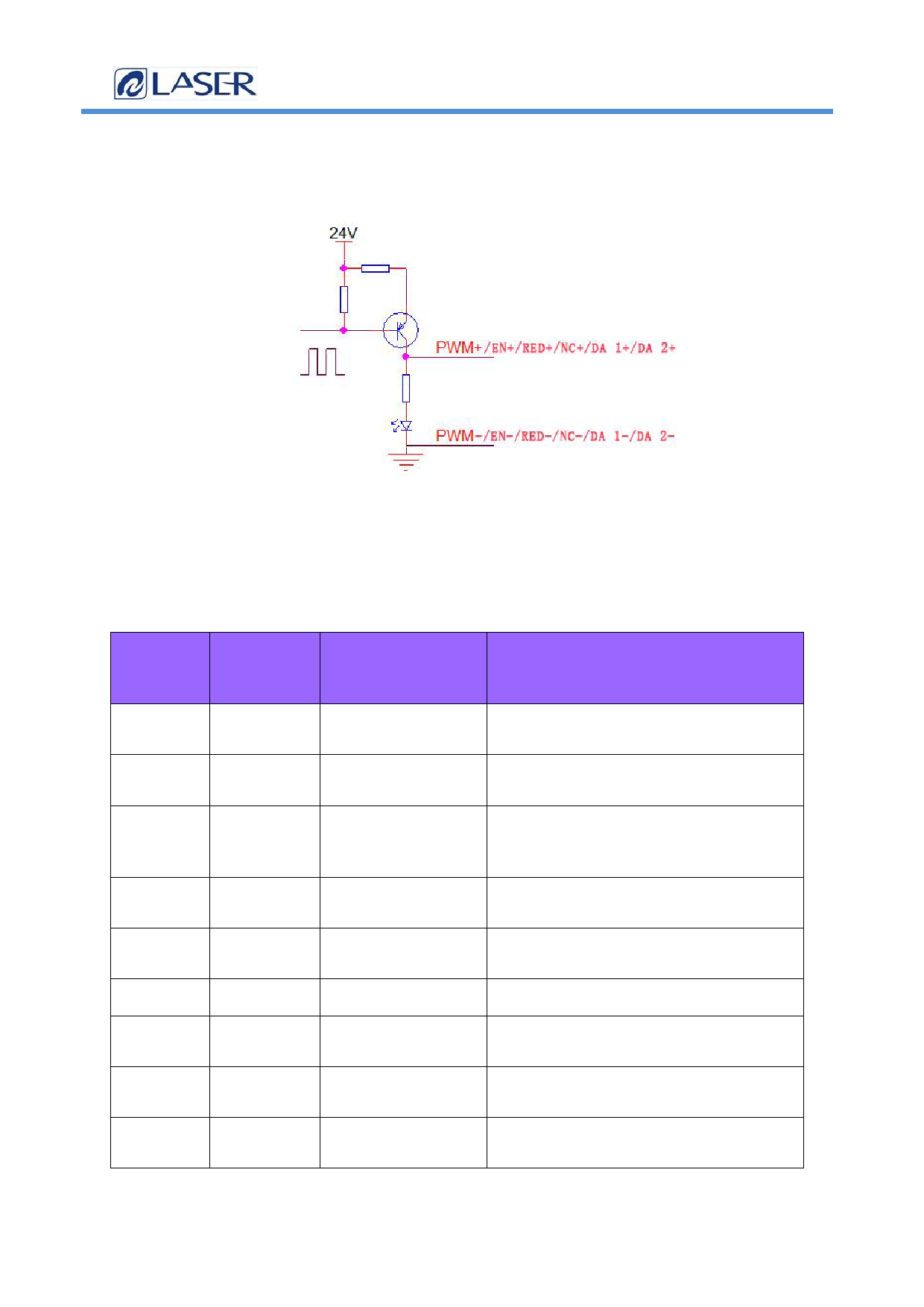
The laser interface is an 8 PIN, green terminal + 4 PIN
green terminal
Figure 2.11 Schematic diagram of the laser control interface
Table 2.11 shows the definition of the laser interface.
Table 2.11
pin
signal
defi
niti
on
expl
ain
1
PWM+
Laser-modulated
Duty cycle 1% -100% adjustable, 24V
signal +
and 5V switchable
2
PWM-
Laser Modulated
Reference to the power source
signal-
3
EN+
Laser enabling
Control laser light signal, high
signal +
level effective, 24V and 5V can be
switched
4
EN-
Laser-enabling
Reference to the power source
signal-
5
RED+
Laser red light
Laser red light control (optional)
signal
6
RED-
GND
Reference to the power source
7
NC+
The laser enables Laser 24V backup port
the backup port
8
NC-
Laser backup port Reference to the power source
ground
9
DA 1+ Analog voltage
For laser peak power regulation, 0-
output +
10V and 0-4V analog voltage selection
177/24
 Qilin BWT20 Double Swing Handheld Laser Welding System User Manual V11 S3")
 Qilin BWT20 Double Swing Handheld Laser Welding System User Manual V11 S3")
 Qilin BWT20 Double Swing Handheld Laser Welding System User Manual V11 S3")
 Qilin BWT20 Double Swing Handheld Laser Welding System User Manual V11 S3")
 Qilin BWT20 Double Swing Handheld Laser Welding System User Manual V11 S3")
 Qilin BWT20 Double Swing Handheld Laser Welding System User Manual V11 S3")
 Qilin BWT20 Double Swing Handheld Laser Welding System User Manual V11 S3")
 Qilin BWT20 Double Swing Handheld Laser Welding System User Manual V11 S3")
 Qilin BWT20 Double Swing Handheld Laser Welding System User Manual V11 S3")