
BWT20 Qilin double swing handheld laser
welding system user maTnauablleV12..07
pin
signal
defi
niti
on
expl
ain
The light condition is met when
1
CF
trigger signal
triggered
2
DT
Guide communication number
The light condition are
achieved when on
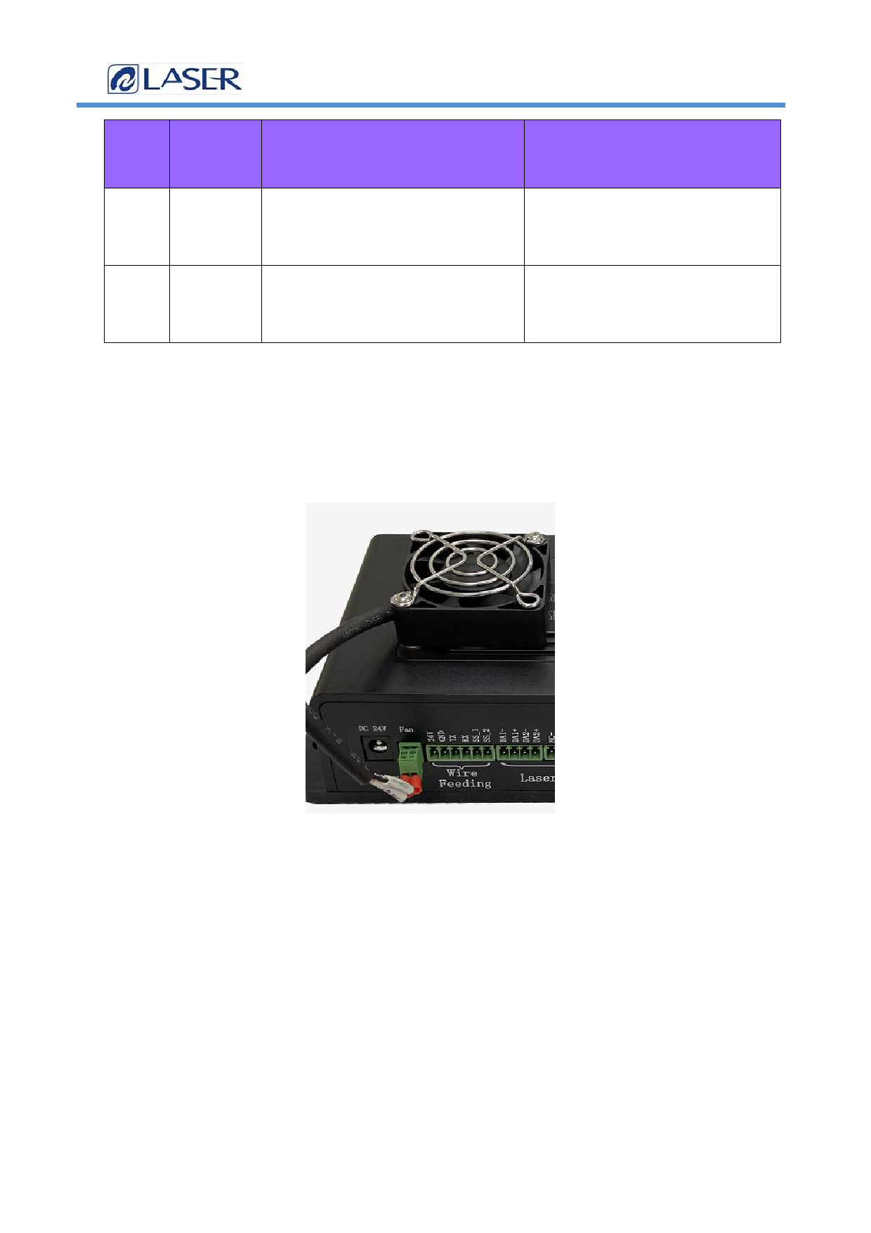
2.8 Introduction of the fan interface
The control box provides a dedicated 24V fan port interface position, independent socket,
not easy to insert wrong.
Figure 2.8 Schematic diagram of the fan interface
2.9 Control interface of the wire feeder
The control box provides a special communication interface for the control wire
feeder, and the 24V power supply is directly connected to the power input end of the
control box and can be provided
3A Current, Table 2.9 defines the control interface of the wire feeder.
147/24
 Qilin BWT20 Double Swing Handheld Laser Welding System User Manual V11 S3")
 Qilin BWT20 Double Swing Handheld Laser Welding System User Manual V11 S3")
 Qilin BWT20 Double Swing Handheld Laser Welding System User Manual V11 S3")
 Qilin BWT20 Double Swing Handheld Laser Welding System User Manual V11 S3")
 Qilin BWT20 Double Swing Handheld Laser Welding System User Manual V11 S3")
 Qilin BWT20 Double Swing Handheld Laser Welding System User Manual V11 S3")
 Qilin BWT20 Double Swing Handheld Laser Welding System User Manual V11 S3")
 Qilin BWT20 Double Swing Handheld Laser Welding System User Manual V11 S3")
 Qilin BWT20 Double Swing Handheld Laser Welding System User Manual V11 S3")