
深圳市睿法智能科技有限公司
6.5 CN2 laser interface
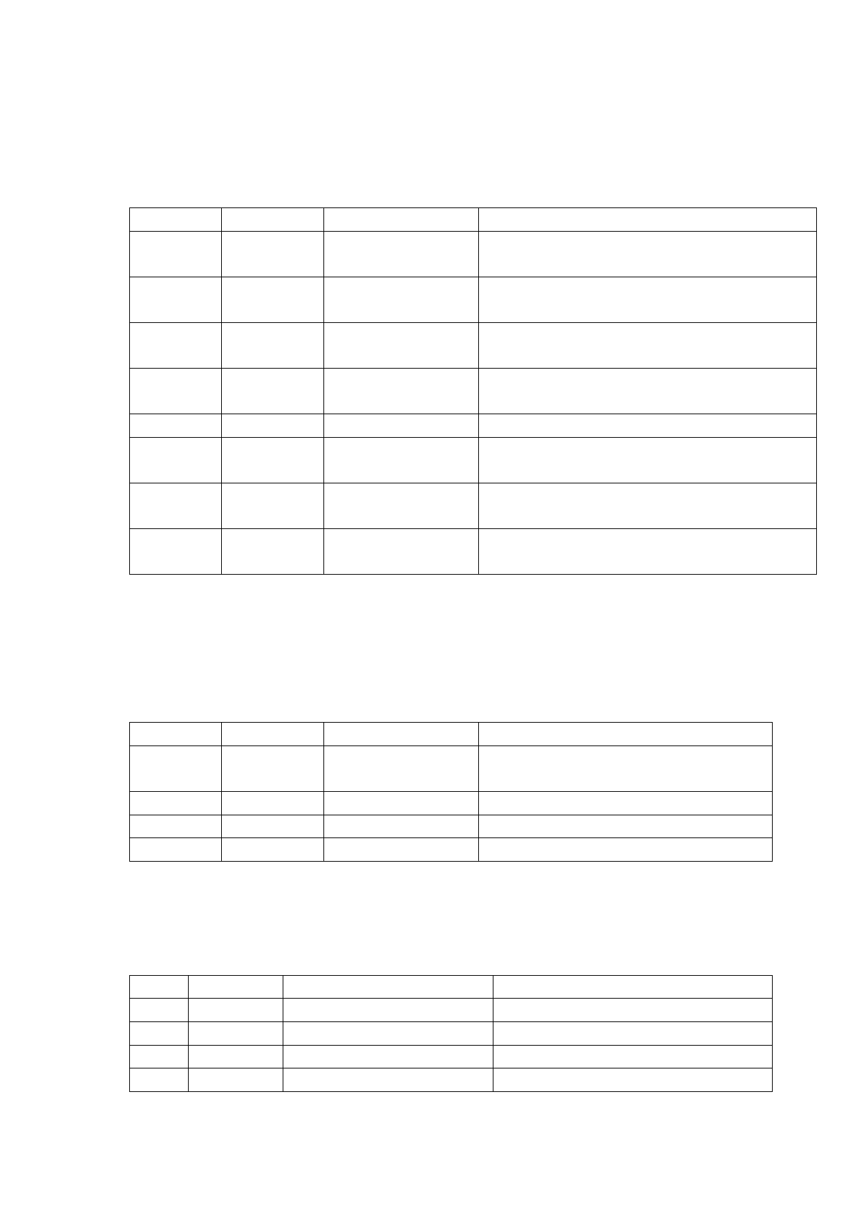
Laser interface is a 8-pin green terminal. Chart 6.5.1 shows the definition of laser
interface.
Chart 6.5.1
Pin
Signal
Definition
Description
Duty cycle from1% to 99% is adjustable, 24V
1
PWM+
Modulating signal+
level
Duty cycle from1% to 99% is adjustable, 24V
2
PWM-
Modulating signal-
level
Analog voltage
0-10 V analog voltage is used for adjustment
3
DA
output
of laser peak power
4
GND
GND
Generally connected with DA- and Enable
terminals
5
OVCC
+24V power output power supply, maximum output 500mA
6
Enable
Laser enable signal
24V level, high level is effective
Laser fault alarm —
7
Alarm
input
Red light indicator Part of laser needs this signal and this
8
GATE
signal
function is reserved before delivery.
6.6 CN3 temperature sensor interface
CN3 temperature sensor interface is a 4-pin green terminal. Users can directly
insert the connecting wire with terminal into this interface. Chart 6.6.1 shows the
definition of temperature sensor interface.
Chart 6.6.1
Pin
Signal
Definition
Description
+5V power supply, maximum output
1
+5V_out
Sensor P interface
500mA
2
Light
Sensor L interface —
3
Temp
Sensor T interface —
4
GND
Sensor G interface —
6.7 HMI touch screen interface
HMI interface is a 4-pin green terminal through which mainboard supplies power
to HMI and communicates with it. Chart 6.7.1 shows the definition of HMI interface.
Chart 6.7.1
Pin Signal
Definition
Description
1
OVCC
+24V power supply, 500mA Power supply by panel
2
TXD_HMI
HMI sending end
Serial communication TXD signal
3
RXD_HMI
HMI receiving end
Serial communication RXD signal
4
GND
GND
—
20
 LaserMaster Versatile, FWH20-S10A Intelligent Single Pendulum Handheld Welding Head 2023-09-13 C")
 LaserMaster Versatile, FWH20-S10A Intelligent Single Pendulum Handheld Welding Head 2023-09-13 C")
 LaserMaster Versatile, FWH20-S10A Intelligent Single Pendulum Handheld Welding Head 2023-09-13 C")
 LaserMaster Versatile, FWH20-S10A Intelligent Single Pendulum Handheld Welding Head 2023-09-13 C")
 LaserMaster Versatile, FWH20-S10A Intelligent Single Pendulum Handheld Welding Head 2023-09-13 C")
 LaserMaster Versatile, FWH20-S10A Intelligent Single Pendulum Handheld Welding Head 2023-09-13 C")
 LaserMaster Versatile, FWH20-S10A Intelligent Single Pendulum Handheld Welding Head 2023-09-13 C")
 LaserMaster Versatile, FWH20-S10A Intelligent Single Pendulum Handheld Welding Head 2023-09-13 C")
 LaserMaster Versatile, FWH20-S10A Intelligent Single Pendulum Handheld Welding Head 2023-09-13 C")