
Page 20 of 30
BWT20 Qilin Wobble Handheld Laser Welding Head
After the wire speed is set, click simulation operation is the set wire speed.
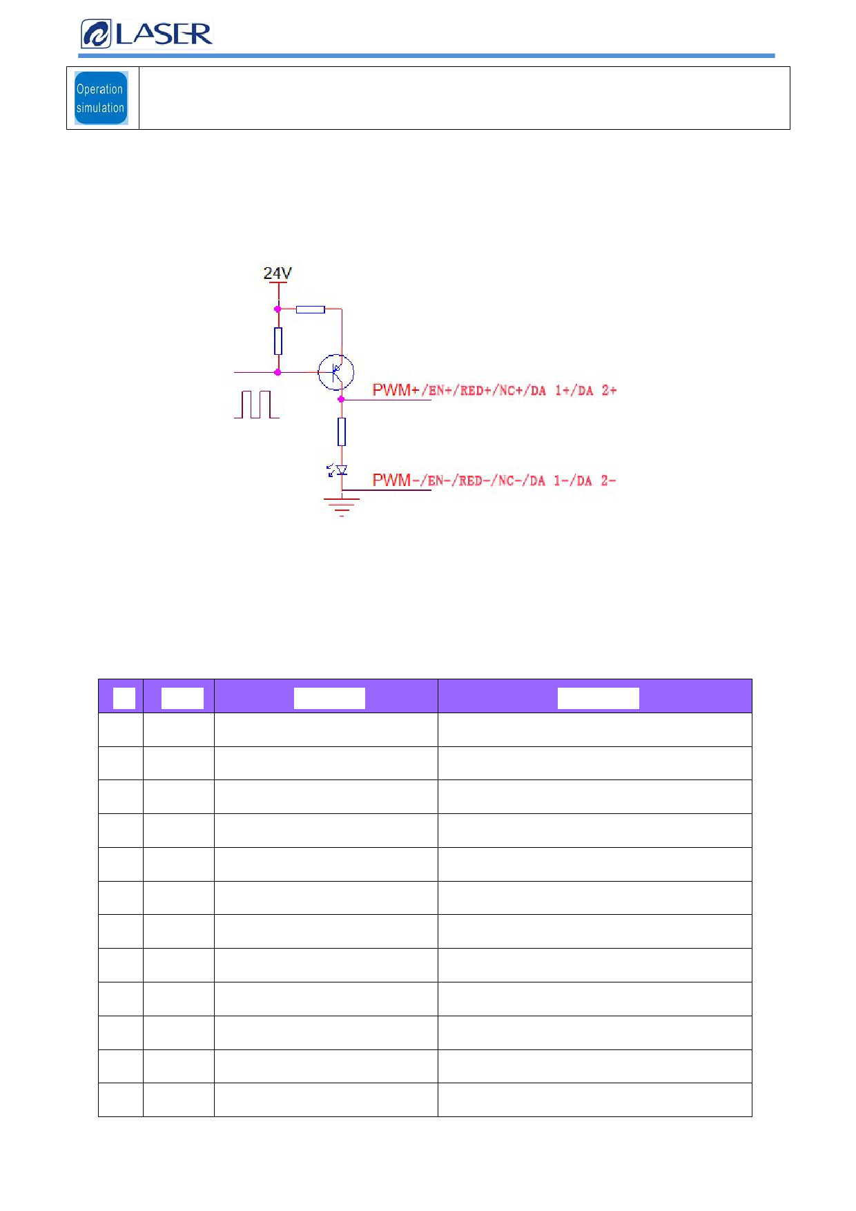
2.11 Laser control interface
The laser interface is an 8PIN green terminal + 4PIN green terminal.
Figure 2.11 Schematic diagram of the laser control interface
Table 2.11 is the definition of the laser interface.
Table 2.11
Pin Signal
1
PWM+
2
PWM-
3
EN+
4
EN-
5
RED+
Definition
Laser-modulated signal +
Laser Modulated signal-
Laser enabling signal +
Laser-enabling signal-
Laser red light signal
Description
Duty cycle is 1% -99% adjustable, 24V and 5V
switchable
Reference place for connecting to the power
source
Control laser light signal, high level effective, 24V
and 5V switchable
Reference place for connecting to the power
source
Laser red light control (not connected)
6
RED-
GND
Reference place for connecting to the power
source
7
NC+ The laser enables the backup ports
Laser 24V spare port
8
NC-
9
DA 1+
10 DA 1-
11 DA 2+
12 DA 2-
Laser backup port ground
Analog voltage output +
Analog voltage output-
Analog voltage output
GND
Reference place for connecting to the power
source
For laser peak power regulation, 0-10V and 0-4V
analog voltages are optional
Reference place for connecting to the power
source
For proportional valve adjustment, 0-10V analog
voltage,
Reference place for connecting to the power
source
Shenzhen Qilin Laser Application Technology Co., Ltd.
 LaserMaster Dedicated, BWT20 Wobble Handheld Laser Welding Head Manual")
 LaserMaster Dedicated, BWT20 Wobble Handheld Laser Welding Head Manual")
 LaserMaster Dedicated, BWT20 Wobble Handheld Laser Welding Head Manual")
 LaserMaster Dedicated, BWT20 Wobble Handheld Laser Welding Head Manual")
 LaserMaster Dedicated, BWT20 Wobble Handheld Laser Welding Head Manual")
 LaserMaster Dedicated, BWT20 Wobble Handheld Laser Welding Head Manual")
 LaserMaster Dedicated, BWT20 Wobble Handheld Laser Welding Head Manual")
 LaserMaster Dedicated, BWT20 Wobble Handheld Laser Welding Head Manual")
 LaserMaster Dedicated, BWT20 Wobble Handheld Laser Welding Head Manual")