
Page 25 of 37
B WT20C Qilin double swing handheld laser cleaning system user
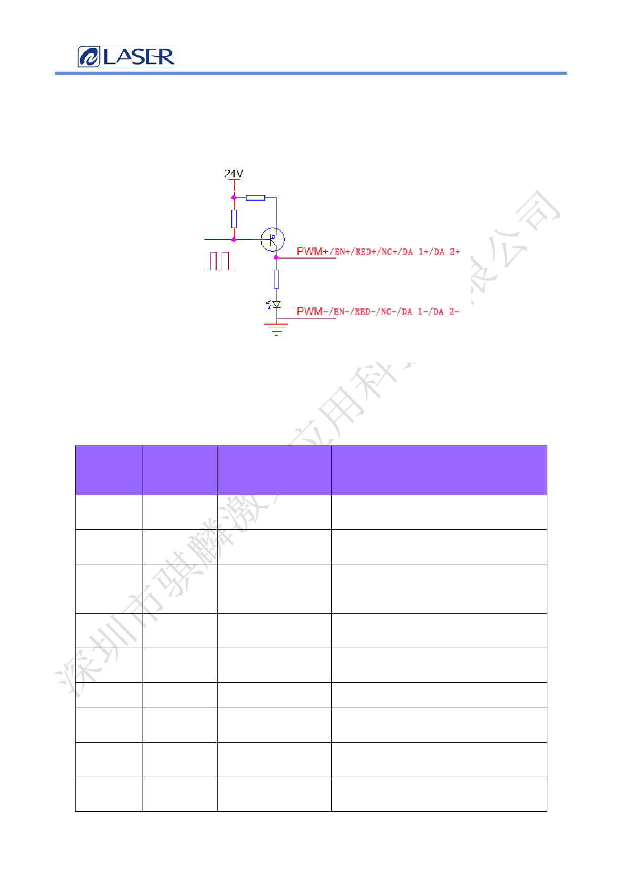
2.10 Laser control interface
The laser interface is an 8 PIN, green terminal + 4 PIN
green terminal
Figure 2.10 Diagram of the laser control interface
Table 2.10 shows the laser interface definition.
Table 2.10
pin
signal
defi
niti
on
expl
ain
1
PWM+
Laser-modulation Duty cycle 0% -100% adjustable, 24V
signal +
and 5V switchable
2
PWM-
Laser Modulated
Reference to the power source
signal-
3
EN+
Laser enabling
Control laser light signal, high
signal +
level effective, 24V and 5V can be
switched
4
EN-
Laser-enabling
Reference to the power source
signal-
5
RED+
Laser red light
Laser red light control (optional)
signal
6
RED-
GND
Reference to the power source
7
NC+
The laser enables Laser 24V backup port
the backup port
8
NC-
Laser backup port Reference to the power source
ground
9
DA 1+ Analog voltage
For laser peak power regulation, 0-
output +
10V and 0-4V analog voltage selection
25Page 22 of 27 pages37
 LaserMaster Dedicated, BWT20 Wobble Handheld Laser Cleaning Head Manual")
 LaserMaster Dedicated, BWT20 Wobble Handheld Laser Cleaning Head Manual")
 LaserMaster Dedicated, BWT20 Wobble Handheld Laser Cleaning Head Manual")
 LaserMaster Dedicated, BWT20 Wobble Handheld Laser Cleaning Head Manual")
 LaserMaster Dedicated, BWT20 Wobble Handheld Laser Cleaning Head Manual")
 LaserMaster Dedicated, BWT20 Wobble Handheld Laser Cleaning Head Manual")
 LaserMaster Dedicated, BWT20 Wobble Handheld Laser Cleaning Head Manual")
 LaserMaster Dedicated, BWT20 Wobble Handheld Laser Cleaning Head Manual")
 LaserMaster Dedicated, BWT20 Wobble Handheld Laser Cleaning Head Manual")