
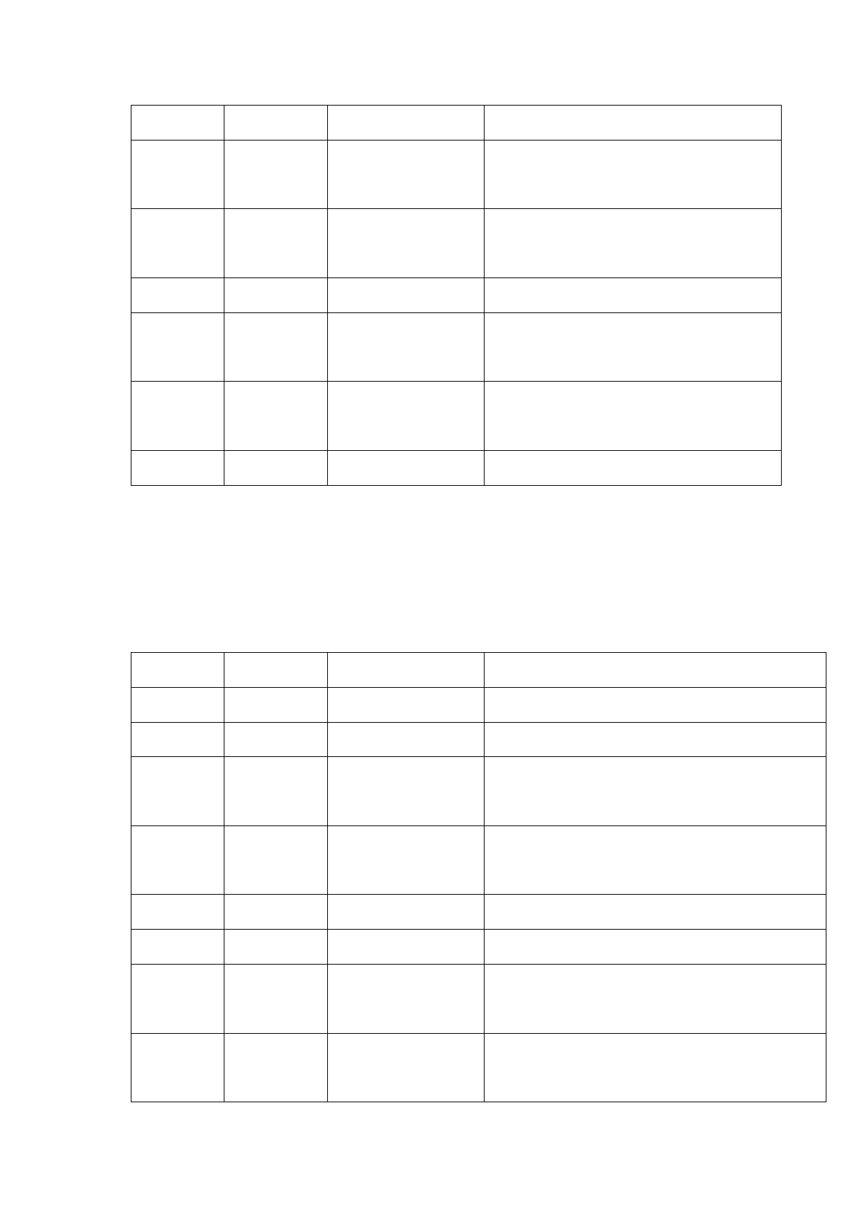
- interface
with driver PUL-
Motor wire feed
Used for motor wire feed and connection
3
DIR+
direction + interface with driver PUL+
Motor wire feed
Used for motor wire feed and connection
4
DIR-
direction - interface with driver Dir
5
GND
Reference ground
—
Wire feed control
Used for automatic wire feed of IO control
6
Feed
interface
wire feeder
Wire drawing control Used for automatic wire feed of IO control
7
Backoff
interface
wire drawing
8
OVCC +24V power output Power supply, maximum output is 500mA
6.5 CN2 laser interface
The laser interface is a 8PIN green terminal. Table 6.5.1 shows the
definition of laser interface.
Table 6.5.1
Pin
Signal
Definition
Description
1
PWM+ Modulating signal+ Duty ratio: 1%-99% (adjustable), 24V level
2
PWM-
Modulating signal-
Duty ratio: 1%-99% (adjustable), 24V level
0-10V analog voltage, used for laser peak power
3
DA
Analog voltage output
adjustment
Power reference
Generally connecting to DA- and Enable-end
4
GND
ground
5
OVCC +24V power output Power supply, maximum output is 500mA
6
Enable Laser enabling signal 24V level and high level: effective
Laser failure alarm
—
7
Alarm
input
The signal is needed by part of lasers. The function
8
GATE
Red light index signal
is reserved for use when leaving the factory
20
 FWH30-D20C 睿法双摆手持焊接头英文说明书(双送丝四合一)A版本 2024-02-24")
 FWH30-D20C 睿法双摆手持焊接头英文说明书(双送丝四合一)A版本 2024-02-24")
 FWH30-D20C 睿法双摆手持焊接头英文说明书(双送丝四合一)A版本 2024-02-24")
 FWH30-D20C 睿法双摆手持焊接头英文说明书(双送丝四合一)A版本 2024-02-24")
 FWH30-D20C 睿法双摆手持焊接头英文说明书(双送丝四合一)A版本 2024-02-24")
 FWH30-D20C 睿法双摆手持焊接头英文说明书(双送丝四合一)A版本 2024-02-24")
 FWH30-D20C 睿法双摆手持焊接头英文说明书(双送丝四合一)A版本 2024-02-24")
 FWH30-D20C 睿法双摆手持焊接头英文说明书(双送丝四合一)A版本 2024-02-24")
 FWH30-D20C 睿法双摆手持焊接头英文说明书(双送丝四合一)A版本 2024-02-24")