
6.3 CN5 power supply interface
The power supply interface falls into 6PIN green terminal, providing
a power interface for mainboard and galvanometer externally, with
voltage: DC 24V (DC 24V) and DC ±15V (DC ±15).
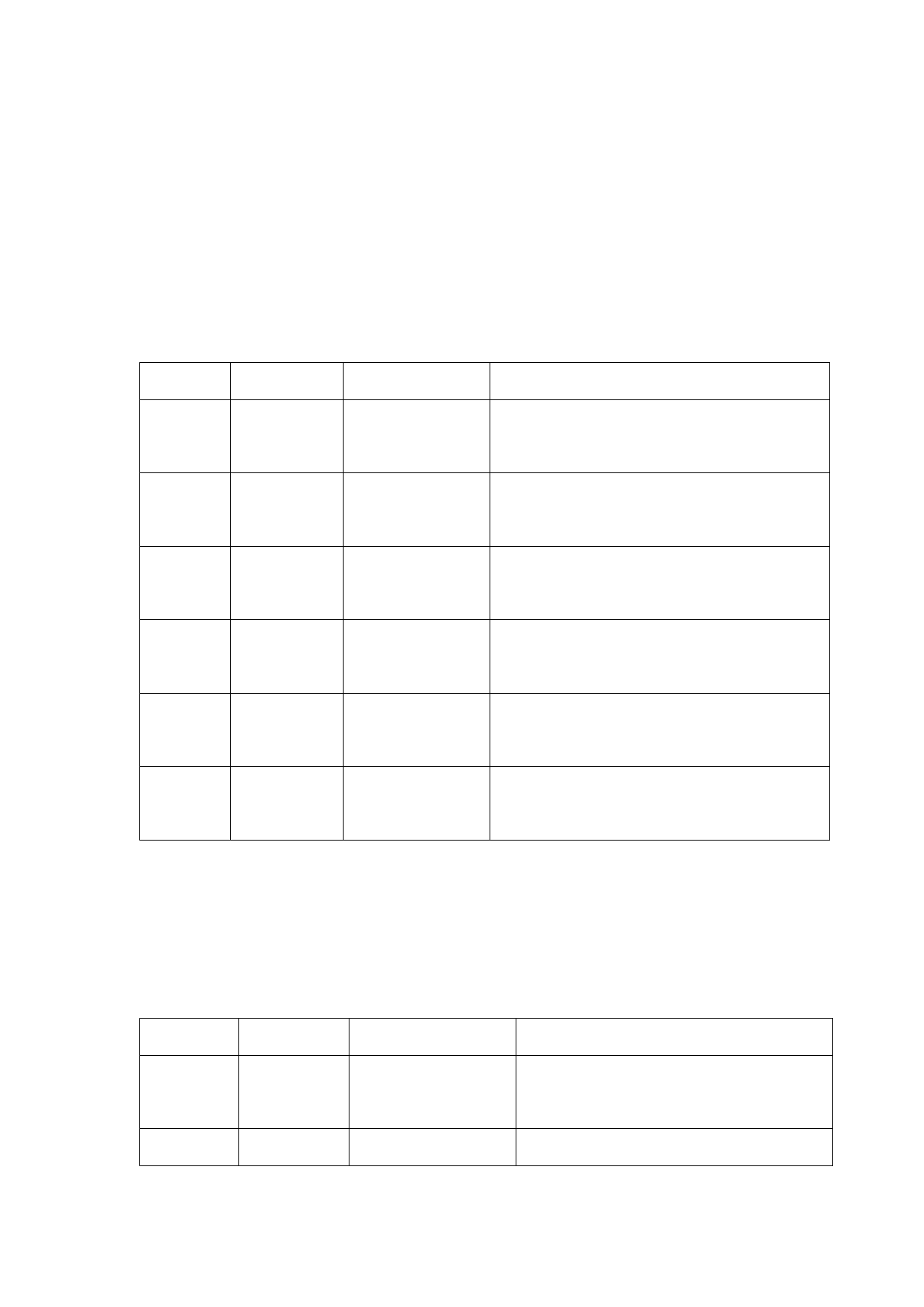
Table 6.3.1 shows the definition of CN5 power supply interface.
Table 6.3.1
Pin
Signal
Definition
Description
+24V external power input and power supply
1
24V+
Power supply input
output current: above 3A
Power reference
2
24V-
—
ground
External shielding
3
PGND
Generally connecting to ground or enclosure
ground
+15V external power input and power supply
4
+15V
Power supply input
output current: above 3A
Power reference
5
GND
—
ground
-15V external power input and power supply
6
-15V
Power supply input
output current: above 3A
6.4 CN1 wire feeder interface
The wire feeder interface CN1 is a 8PIN green terminal, supporting
motor wire feed and IO wire feed. Table 6.4.1 shows the definition of
wire feeder interface.
Table 6.4.1
Pin
Signal
Definition
Description
Motor wire feed pulse Used for motor wire feed and connection
1
Pulse+
+ interface
with driver PUL+
2
Pulse-
Motor wire feed pulse Used for motor wire feed and connection
19
 FWH30-D20C 睿法双摆手持焊接头英文说明书(双送丝四合一)A版本 2024-02-24")
 FWH30-D20C 睿法双摆手持焊接头英文说明书(双送丝四合一)A版本 2024-02-24")
 FWH30-D20C 睿法双摆手持焊接头英文说明书(双送丝四合一)A版本 2024-02-24")
 FWH30-D20C 睿法双摆手持焊接头英文说明书(双送丝四合一)A版本 2024-02-24")
 FWH30-D20C 睿法双摆手持焊接头英文说明书(双送丝四合一)A版本 2024-02-24")
 FWH30-D20C 睿法双摆手持焊接头英文说明书(双送丝四合一)A版本 2024-02-24")
 FWH30-D20C 睿法双摆手持焊接头英文说明书(双送丝四合一)A版本 2024-02-24")
 FWH30-D20C 睿法双摆手持焊接头英文说明书(双送丝四合一)A版本 2024-02-24")
 FWH30-D20C 睿法双摆手持焊接头英文说明书(双送丝四合一)A版本 2024-02-24")