
Page 12 of 37
4.3 Disassembly and assembly of optics lens
4.3.1 Disassembly and assembly of collimation lens
Tools: 2mm inner-hexagon wrench, dust-free cotton swab, alcohol
※ The disassembly and assembly shall be completed in a clean place.
When the lens are dismounted, the dust-free gloves or dust-free
fingerstall.
※ Disassembly and assembly steps:
Step 1: Clean up all the dust on the surface of the laser head firstly.
Step 2: Loosen the M2.5 hex socket head cap screw in the figure by hand
with a 2mm hex wrench.
Step 3: Remove the collimation handle horizontally, and pull out the
collimation drawer module.
Step 4: Seal the port with textured paper to prevent the dust from
entering the cavity, resulting in pollution.
Step 5: Rotate the gland for 90° after pressing it downward gently
and take out the gland by two bosses aligning to left/right opening to
replace the collimation lens.
(Note: orientation of installed lens in the concave and convex
direction)
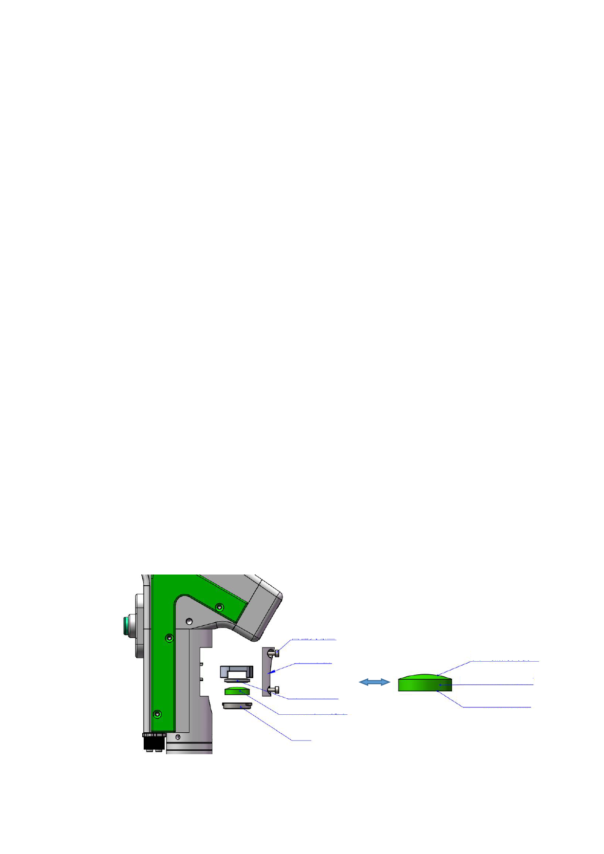
M2.5 hex socket head
cap screw
Collimation handle
16.5*12*2.3
elastic sealing ring
D16*F50 collimation lens
Cap pressing
The surface which is
more convex shall be
upward
D16*F50 collimation
lens
The face which is flatter shall
be downward
12
 FWH30-D20C 睿法双摆手持焊接头英文说明书(双送丝四合一)A版本 2024-02-24")
 FWH30-D20C 睿法双摆手持焊接头英文说明书(双送丝四合一)A版本 2024-02-24")
 FWH30-D20C 睿法双摆手持焊接头英文说明书(双送丝四合一)A版本 2024-02-24")
 FWH30-D20C 睿法双摆手持焊接头英文说明书(双送丝四合一)A版本 2024-02-24")
 FWH30-D20C 睿法双摆手持焊接头英文说明书(双送丝四合一)A版本 2024-02-24")
 FWH30-D20C 睿法双摆手持焊接头英文说明书(双送丝四合一)A版本 2024-02-24")
 FWH30-D20C 睿法双摆手持焊接头英文说明书(双送丝四合一)A版本 2024-02-24")
 FWH30-D20C 睿法双摆手持焊接头英文说明书(双送丝四合一)A版本 2024-02-24")
 FWH30-D20C 睿法双摆手持焊接头英文说明书(双送丝四合一)A版本 2024-02-24")