
Page 18 of 37
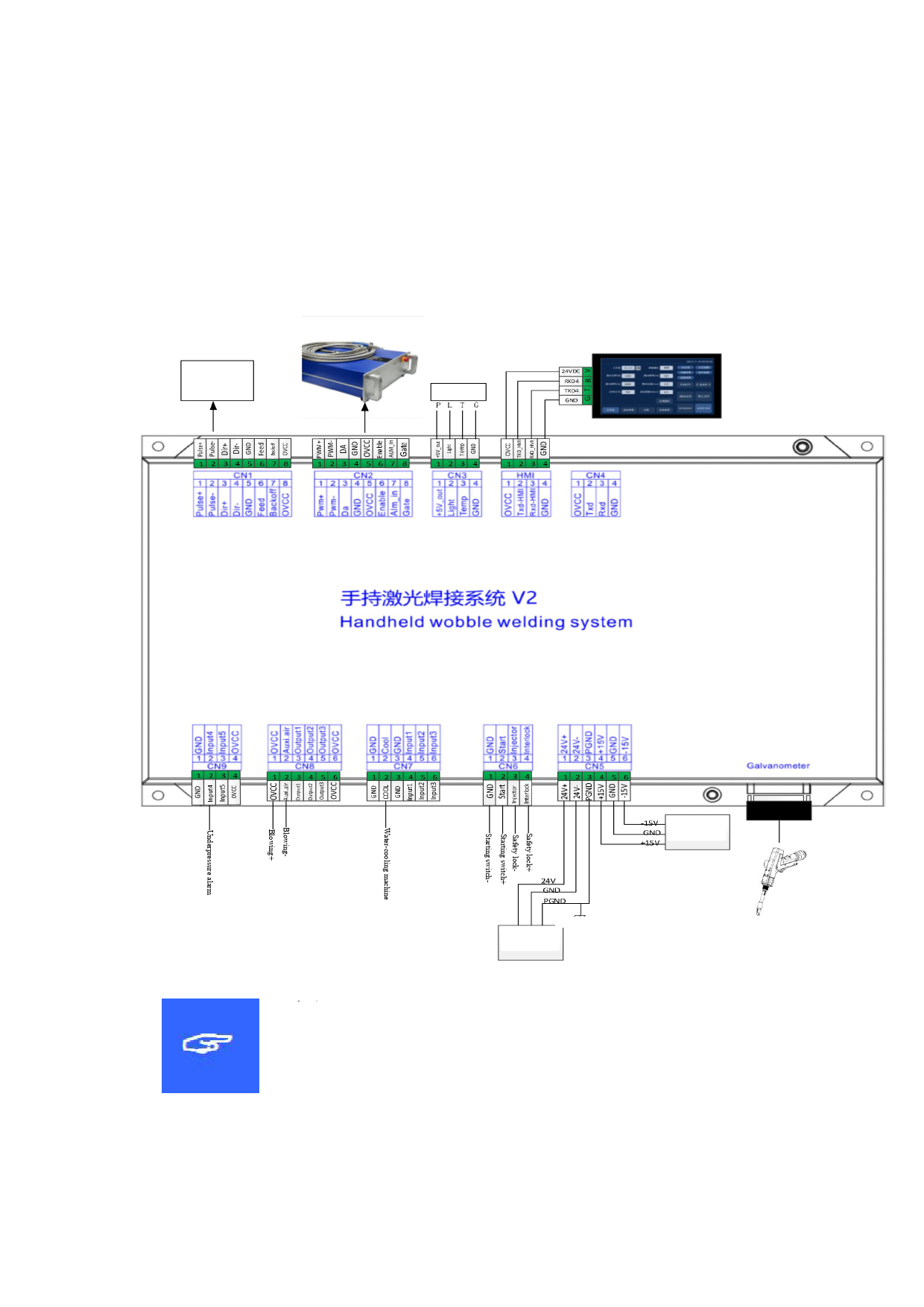
6.2 System wiring
The following figure is a schematic diagram for wiring of the whole
system. Refer to the schematic diagram for system wiring. Refer to
relevant chapters for detailed interface definition.
Wire feeder
Temperature
sensor
Temperature
sensor
±15V DC power
supply
Connecting to the ground or
enclosure
24V DC power
supply
Note:
Don't connect the reserved pin in the mainboard.
18
 FWH30-D10C 睿法双摆手持焊接头英文说明书(单送丝四合一)A版本 2024-02-24")
 FWH30-D10C 睿法双摆手持焊接头英文说明书(单送丝四合一)A版本 2024-02-24")
 FWH30-D10C 睿法双摆手持焊接头英文说明书(单送丝四合一)A版本 2024-02-24")
 FWH30-D10C 睿法双摆手持焊接头英文说明书(单送丝四合一)A版本 2024-02-24")
 FWH30-D10C 睿法双摆手持焊接头英文说明书(单送丝四合一)A版本 2024-02-24")
 FWH30-D10C 睿法双摆手持焊接头英文说明书(单送丝四合一)A版本 2024-02-24")
 FWH30-D10C 睿法双摆手持焊接头英文说明书(单送丝四合一)A版本 2024-02-24")
 FWH30-D10C 睿法双摆手持焊接头英文说明书(单送丝四合一)A版本 2024-02-24")
 FWH30-D10C 睿法双摆手持焊接头英文说明书(单送丝四合一)A版本 2024-02-24")