
Page 26 of 35
Shenzhen RelFar Intelligent Technology Co., Ltd.
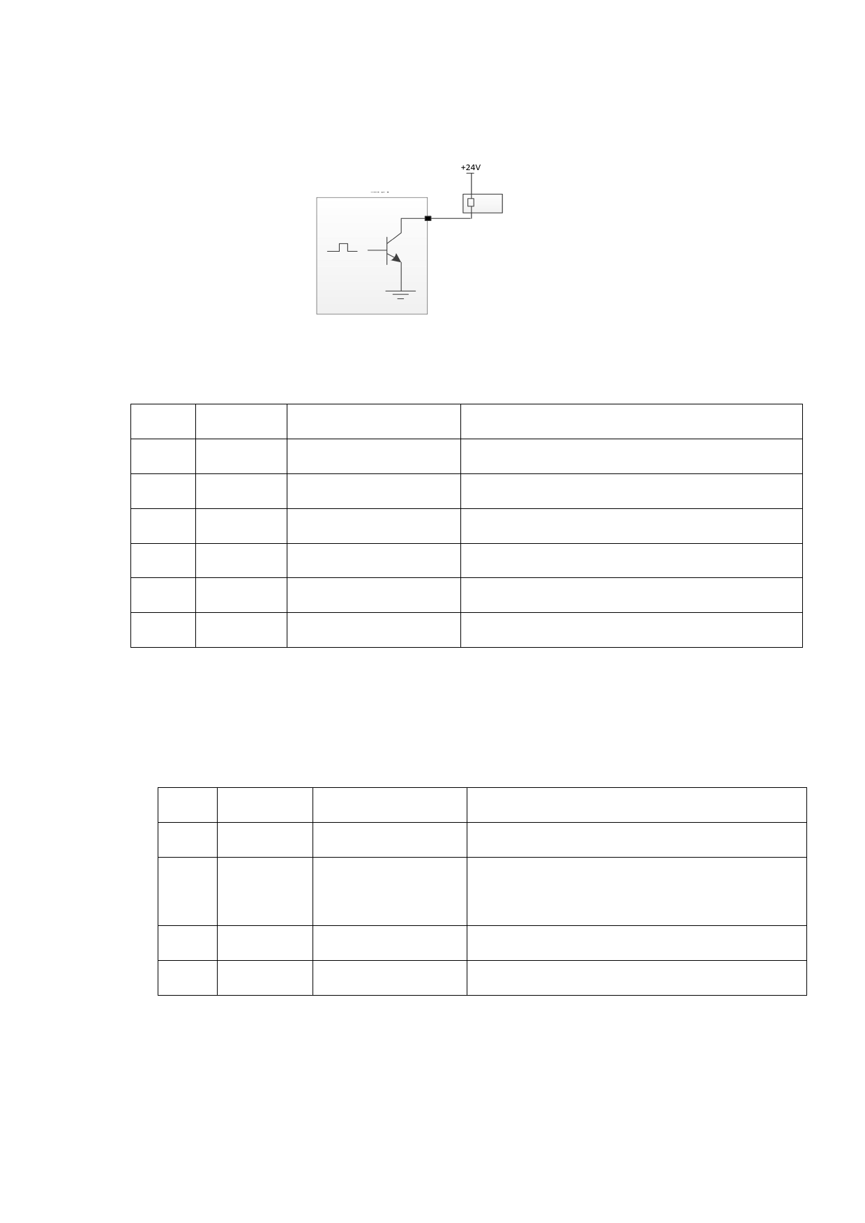
used to directly drive the relay and the maximum current can reach to
500mA. Table 6.11.1-Schematic Diagram for Wiring is as follows:
Mainboard
24V relay
Schematic Diagram for Output Port
Pin
Signal
Table 6.11.1
Definition
Instructions
1
OVCC +24V power output
Power supply, maximum output: 500mA
2
Auxi.air Protective gas
Used for protective gas blowing control
3
Output1 Green light
—
4
Output2 Red light
—
5
Output3 Buzzer
—
6
OVCC +24V power output
Power supply, maximum output: 500mA
6.12 CN9 common input interface 2
The CN9 interface is a 4PIN green terminal. Table 6.12.1 shows the
definition of CN9 interface.
Table 6.12.1
Pin
Signal
Definition
Instructions
1
GND Reference ground
—
Underpressure alarm
2
Input4
input
3
Input5 Reserved
—
4
OVCC +24V power output Power supply, maximum output: 500mA
6.13 Galvanometer interface
The system provides two DB9 galvanometer interfaces, one DB9
male and one DB9 female.
26
 FWH20-DC30A 智能双摆手持清洗头英文说明书 B版本 2023-11-30")
 FWH20-DC30A 智能双摆手持清洗头英文说明书 B版本 2023-11-30")
 FWH20-DC30A 智能双摆手持清洗头英文说明书 B版本 2023-11-30")
 FWH20-DC30A 智能双摆手持清洗头英文说明书 B版本 2023-11-30")
 FWH20-DC30A 智能双摆手持清洗头英文说明书 B版本 2023-11-30")
 FWH20-DC30A 智能双摆手持清洗头英文说明书 B版本 2023-11-30")
 FWH20-DC30A 智能双摆手持清洗头英文说明书 B版本 2023-11-30")
 FWH20-DC30A 智能双摆手持清洗头英文说明书 B版本 2023-11-30")
 FWH20-DC30A 智能双摆手持清洗头英文说明书 B版本 2023-11-30")