
Page 24 of 35
Shenzhen RelFar Intelligent Technology Co., Ltd.
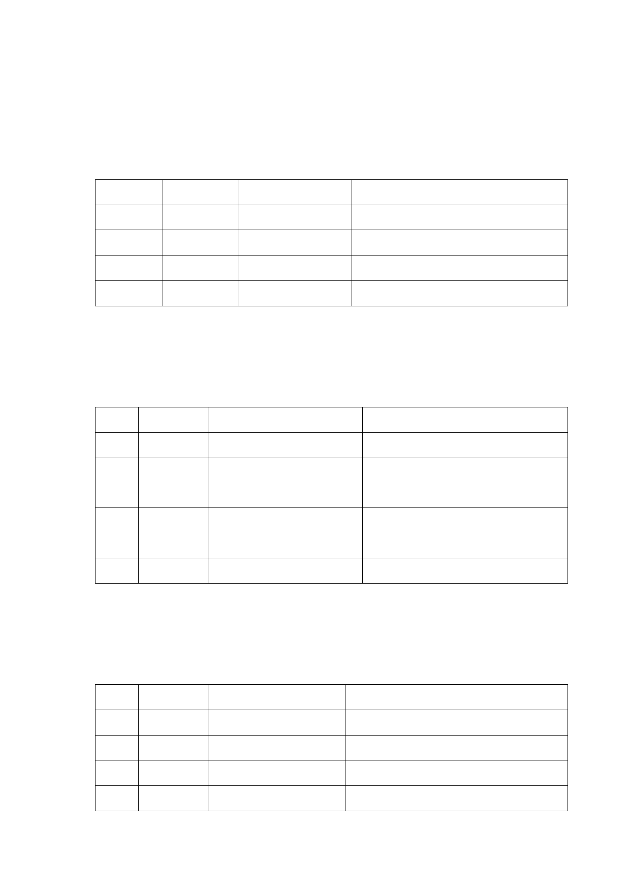
6.6 CN3 temperature sensor interface
The temperature sensor interface CN3 is a 4PIN green terminal.
Table 6.6.1 shows the definition of temperature sensor. The user directly
inserts the supporting connection line with terminal.
Table 6.6.1
Pin
Signal
Definition
Instructions
1
+5V_out Sensor P interface
+5V power supply, maximum output: 500mA
2
Light
Sensor L interface
—
3
Temp
Sensor T interface
—
4
GND
Sensor G interface
—
6.7 HMI touch screen interface
The HMI interface is a 4PIN green terminal and power supply to and
communication with HMI by the mainboard are performed via the port.
Table 6.7.1 shows the definition of HMI interface.
Table 6.7.1
Pin
Signal
Definition
Instructions
1
OVCC +24V power output, 500mA
Panel power supply
Connecting to the HMI sending Serial port communication TXD signal
2
TXD_HMI
end
Connecting to the HMI
3 RXD_HMI
receiving end
Serial port communication RXD signal
4
GND
Power reference ground
—
6.8 CN4 reserved serial interface
The reserved serial port CN4 interface falls into 4PIN green terminal,
with no connection reserved. Table 6.8.1 shows the definition of CN4
interface.
Table 6.8.1
Pin
Signal
Definition
Instructions
1
OVCC +24V power output,500mA Power supply
2
TXD
TXD signal
Serial port communication TXD signal
3
RXD
TXD signal
Serial port communication RXD signal
4
GND
Power reference ground
—
24
 FWH20-DC30A 智能双摆手持清洗头英文说明书 B版本 2023-11-30")
 FWH20-DC30A 智能双摆手持清洗头英文说明书 B版本 2023-11-30")
 FWH20-DC30A 智能双摆手持清洗头英文说明书 B版本 2023-11-30")
 FWH20-DC30A 智能双摆手持清洗头英文说明书 B版本 2023-11-30")
 FWH20-DC30A 智能双摆手持清洗头英文说明书 B版本 2023-11-30")
 FWH20-DC30A 智能双摆手持清洗头英文说明书 B版本 2023-11-30")
 FWH20-DC30A 智能双摆手持清洗头英文说明书 B版本 2023-11-30")
 FWH20-DC30A 智能双摆手持清洗头英文说明书 B版本 2023-11-30")
 FWH20-DC30A 智能双摆手持清洗头英文说明书 B版本 2023-11-30")