
Shenzhen RelFar Intelligent Technology Co., Ltd.
6.2 System wiring
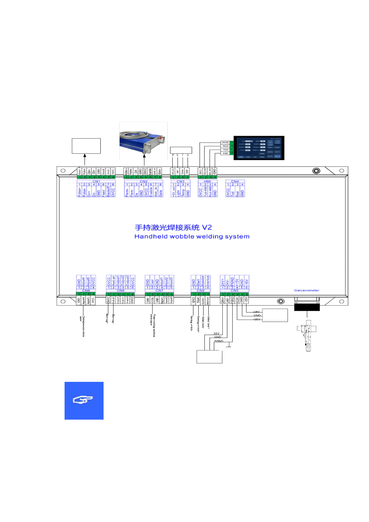
The following figure is a schematic diagram for wiring of the whole
system. Refer to the schematic diagram for system wiring. Refer to
relevant chapters for detailed interface definition.
Wire feeder
Temperature sensor
±15V DC power
supply
Connecting to the ground or enclosure
24V DC power supply
Note:
Don't connect the reserved pin in the mainboard.
21
 FWH20-DC30A 智能双摆手持清洗头英文说明书 B版本 2023-11-30")
 FWH20-DC30A 智能双摆手持清洗头英文说明书 B版本 2023-11-30")
 FWH20-DC30A 智能双摆手持清洗头英文说明书 B版本 2023-11-30")
 FWH20-DC30A 智能双摆手持清洗头英文说明书 B版本 2023-11-30")
 FWH20-DC30A 智能双摆手持清洗头英文说明书 B版本 2023-11-30")
 FWH20-DC30A 智能双摆手持清洗头英文说明书 B版本 2023-11-30")
 FWH20-DC30A 智能双摆手持清洗头英文说明书 B版本 2023-11-30")
 FWH20-DC30A 智能双摆手持清洗头英文说明书 B版本 2023-11-30")
 FWH20-DC30A 智能双摆手持清洗头英文说明书 B版本 2023-11-30")