
LMC2014 users' manual_Fiber
R1
Vin
12
1 1000
Ω
2.3.3 Out0——Out7
Out0/1/2/3 are TTL signal. Out4/5/6/7 can be configured as OC outputs or TTL outputs
through jumper/
If a output is in TTL mode, The output must not be short circuited or wire to GND directly.
Otherwiser the board can be damaged.
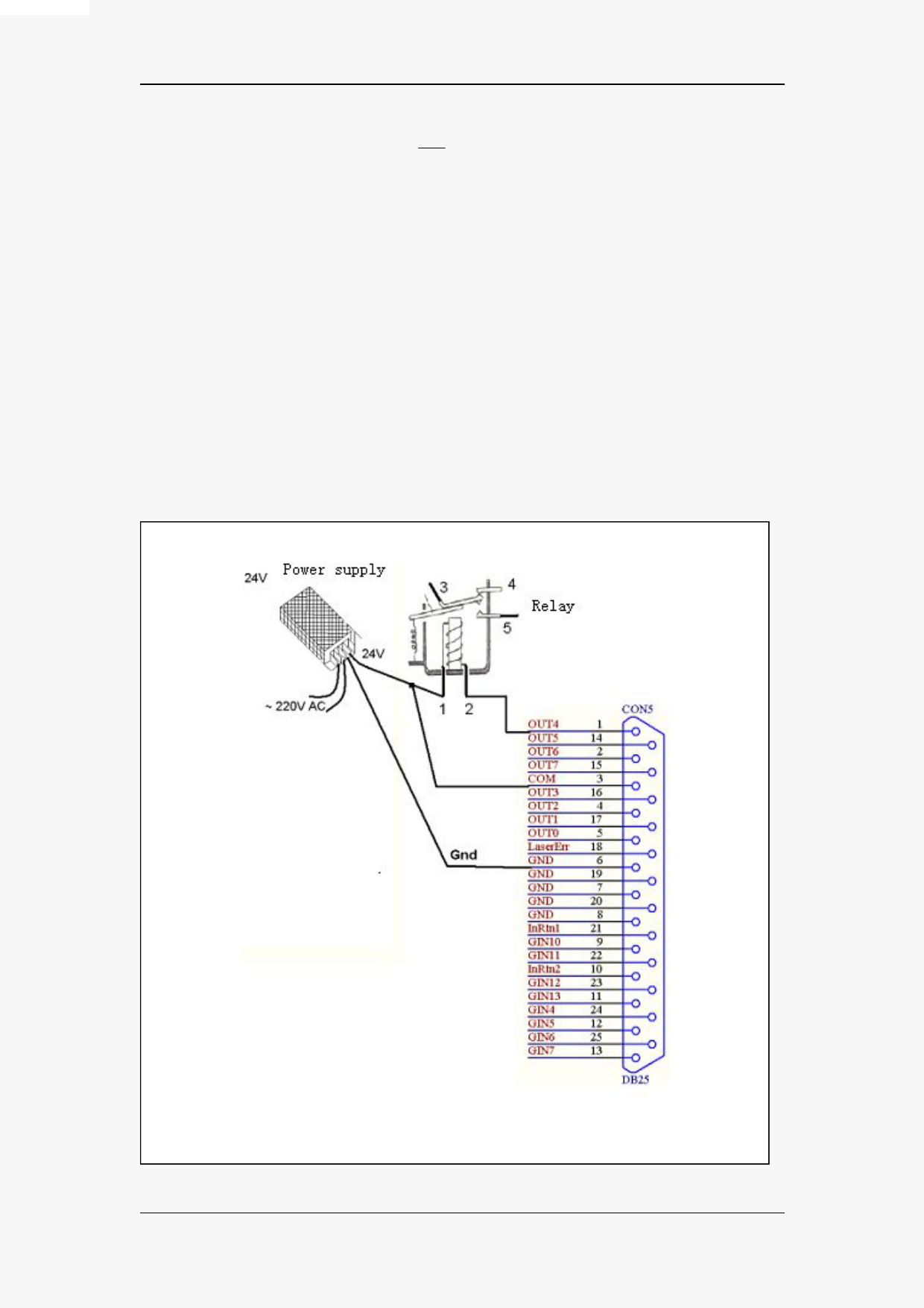
If a output is in OC mode, the typical wiring diagram is shown below, if you want to drive a
inductive instrument, the COM signal(PIN3) must be wired to the anode of the power supply. The
maximum driving current and voltage are 250mA and 40V respectively.
Fig 2- 11 OC output with relay connection
E-document owned By JCZ, Beijing
14
All rights reserved.
 LMC2014 Fiber-Laser-Control-Board")