
LMC2014 users' manual_Fiber
Pic 2-8 recommended wiring for general input pins
For these pins the resistor of the switch should be below 100ohm.
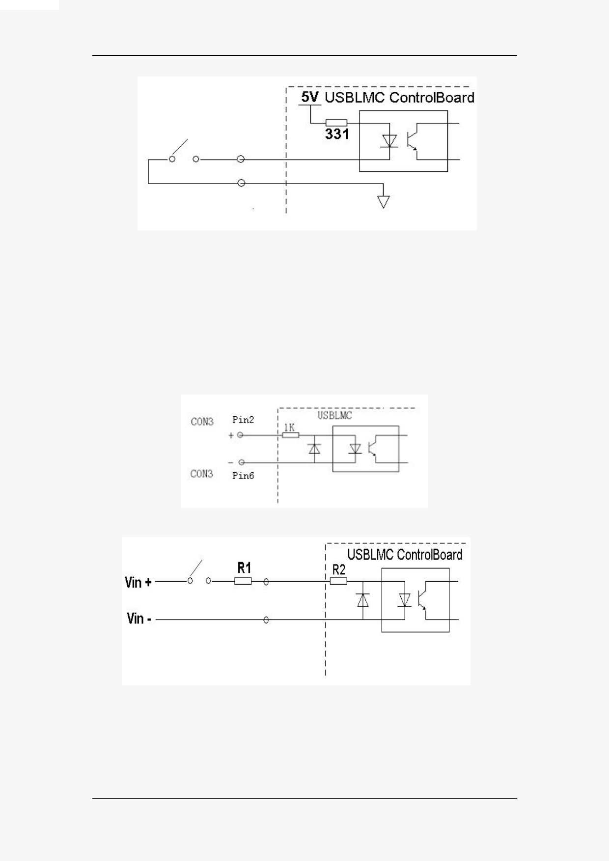
2.3.2 input signal In9-In13
The typical and recommend wiring of general input signals In9-In13 are shown in pic 2-9 and
2-10.
Pic 2-9 typical wiring for general
Pic 2-10 recommended wiring for general input pin in9
Wether to introduce R1 depends on the voltage. The goal here is to ensure that the input
current is between 10mA and 15mA. If the voltage is over 12V, we recommend a current-limiting
resistor. Assume that the current you choose is 12mA, then the resistor is calculated as follow:
E-document owned By JCZ, Beijing
13
All rights reserved.
 LMC2014 Fiber-Laser-Control-Board")