
LMC2014 users' manual_Fiber
JP5, JP6,
JP7
2
JP8, JP9,
JP10,JP11
3
connect control card’s DIR- 、 DIR+ 、 PUL- 、 PUL+ to step
driver’s DIR-、DIR+、PUL-、PUL+;Short connecting JUMPER
pin2-3 will make direction/pulse signals level outputs. In this
case, respectively connect control card’s VCC、DIR+、PUL+ to
step driver’s VCC、DIR、PUL。
Index numbers 0~7. Differentiate various cards when
muti-cards are used at a time. JP8 –JP7- JP6 respectively
correspond to binary b2 b1 b0. Short connecting JUMPER
means 0, and not short connecting it means 1.
These jumper is used to setup the output mode for output 4-7.
If those 1-2 pins are shorted then the output is at TTL mode,
otherwise if 2-3 pins are connected it will be a OC output, these
4 pins represent OUT4,5,6,7 is the same descending order.
Default settings are:
JP1——JP4:2-3 are shorted. The extension axis is signal is in a common anode mode.
JP5——JP7:not connected.
JP8——JP11:2-3 pin shorted, OC output.
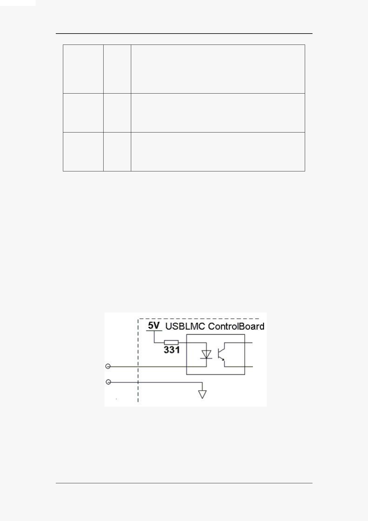
2.3 wiring for digital I/O.
2.3.1 I/O that can be connect to GND
As name suggested these kind of I/O can be connected to switch and then to the ground.
In4-8,XORG0,YORG0, Remark are of these kind.
The following schematics are typical wiring for these kind of signal.
Pic 2-7 wiring for general input pins
E-document owned By JCZ, Beijing
12
All rights reserved.
 LMC2014 Fiber-Laser-Control-Board")