18
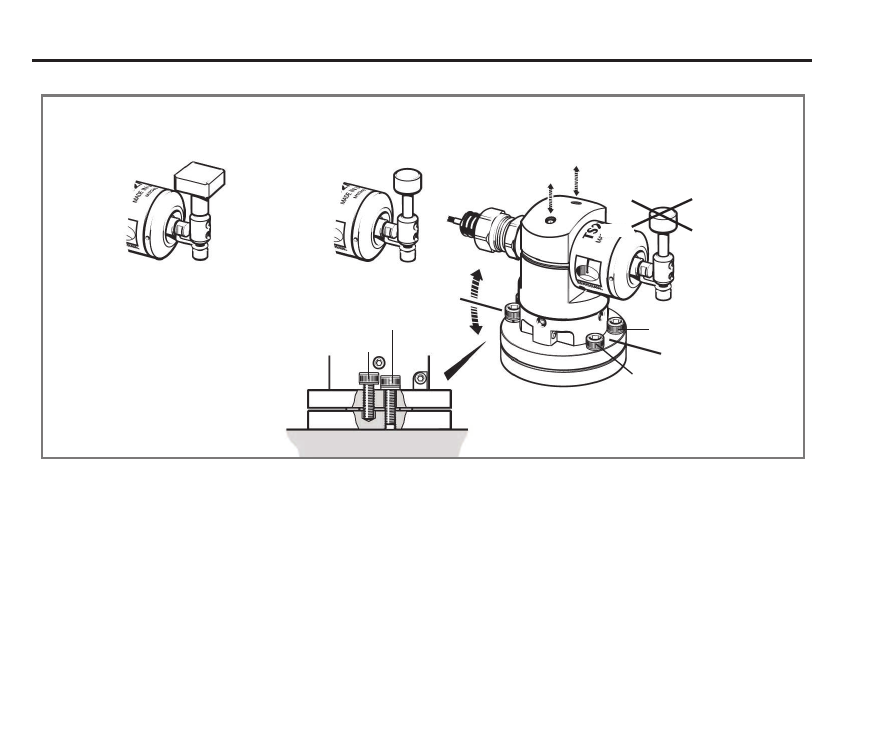
Stylus level setting
CAUTION: Do not stress the break stem
L3 and L4
2.5 mm A/F
Square stylus Disc stylus
0.7 Nm – 0.9 Nm
L4 (0.52 lbf.ft – 0.66 lbf.ft)
L3
Back
Side
Side
Front
H, L1 and L2
L1
4 mm A/F
Screw with
4.6 Nm – 5.6 Nm
(3.40 lbf.ft – 4.13 lbf.ft)
spring washer
L2
H
H
Stylus types
Disc stylus
Square stylus
Ø12.7 mm (Ø0.5 in)
19.05 mm × 19.05 mm
(0.75 in × 0.75 in).
Stylus level setting
The top surface of the stylus must be set level,
front to back and side to side.
The front to back stylus level is obtained by
alternately adjusting screws L1 and L2, which
causes the probe cable end to rise or lower,
changing the stylus level setting. When a level
stylus surface is obtained, tighten screws L1 and L2.
Side to side level is obtained by alternately
adjusting grubscrews L3 and L4, which causes
the probe module to rotate and change the
stylus level setting. When a level stylus surface is
obtained, tighten screws L3 and L4.

