Page 14 of 36
10
Installation
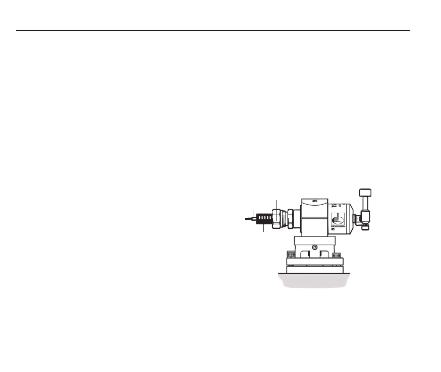
Mounting the probe on the machine table Cable
1. Select a position for the probe on the machine
table.
2. Detach the probe base and the plinth from the
probe by removing the two screws H and the
screw L1 using a 4 mm A/F hexagon key.
3. Fit the T bolt (not supplied by Renishaw).
4. Tighten the T bolt to secure the probe base to
the machine table.
5. Refit the probe and plinth onto the base
and fit the screws. Tighten the two screws H
firmly. Keep the adjusting screws L1 and L2
loose before setting the stylus alignment (see
page 18).
6. Fit the stylus (see pages 16 and 17).
Four-core 7/0.2 polyurethane insulated and
screened cable 10 m (32.8 ft) long. Cable
diameter 4.4 mm (0.17 in). Probe circuit – red and
blue cores (yellow and green not used).
Extension cable (15 m [49 ft] maximum extension)
Maximum permitted cable length:
Probe to interface – 25 m (82 ft) long
Two-core 7/0.2 mm polyurethane insulated and
screened cable. Maintain the screen through the
joins.
Conduit adaptor
Cable
Spirol® pins (see page 9)
The T bolt provides adequate clamping for all
normal circumstances. However two Spirol®
pins (supplied in the probe kit) may be fitted
on installations where there is a requirement
to remove and remount the TS27R. To fit the
Spirol® pins, drill two holes in the machine table
to correspond with two of the probe base holes.
Place the Spirol® pins in the holes and refit the
probe base.
Conduit

