ACD320 user manual
Parameter Description
command channel.
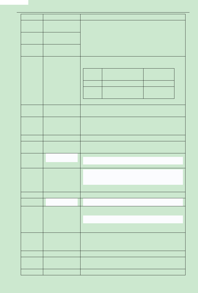
Multi-speed terminal
12
1
8 stages speed can be set up via these 3 terminals digital state
13
Multi-speed terminal combination.
2
Note:multi-speed 1 is the low position, and multi-speed 3 is the
Multi-speed terminal high position.
14
3
2 kinds ofACCE/DCCE time can be chosen via these two terminals
digital state combination.
ACC/DCC time
Terminal
Parameter
ACCE/DCCE time
selection
15
selection terminal
OFF
ACCE time 0
F0.08、F0.09
ACCE time 1
F4.00、F4.01
N
PID is temporarily out of work, and the inverter keeps its current
16
PID control pause
frequency output
The inverter pauses at its current output frequency.After this
17
Traverse pause
function is cancelled, continue to start its traverse operation at its
current frequency.
18
Traverse reset
The inverter is back to its center frequency output.
Acceleration/
Ensure the inverter is not interfered by external signals ( excluding
19
Deceleration forbid stop command ), maintaining its current output frequency.
20
External sleep signal Please refer to F7.28 for detailed description.
23
21,22,24
25
One driving two
circularly water
supply mode is
ineffective
Reserved
Simple PLC run reset
One driving two circularly water supply mode is ineffective, and it
is used in the case of manual operation.
To restore the PLC run to initial state.
26
Simple PLC run
PLC run pause.
ineffective
No matter which value F0.03 is set, frequency setting channel is
Switch to the set of
27
ACI effective when terminal is closed, and F0.03 run command
ACI frequency.
channel recover after terminal isopened.
28
Jog key
Jog run according to current status(forward or reverse)
Torque control
The inverter switch the control mode from torque control to speed
29
forbidden
comtrol.
30
Frequency
When terminal is closed, the frequency value UP/DOWN has set is
- 71-

