ACD320user manual
Installation and wiring
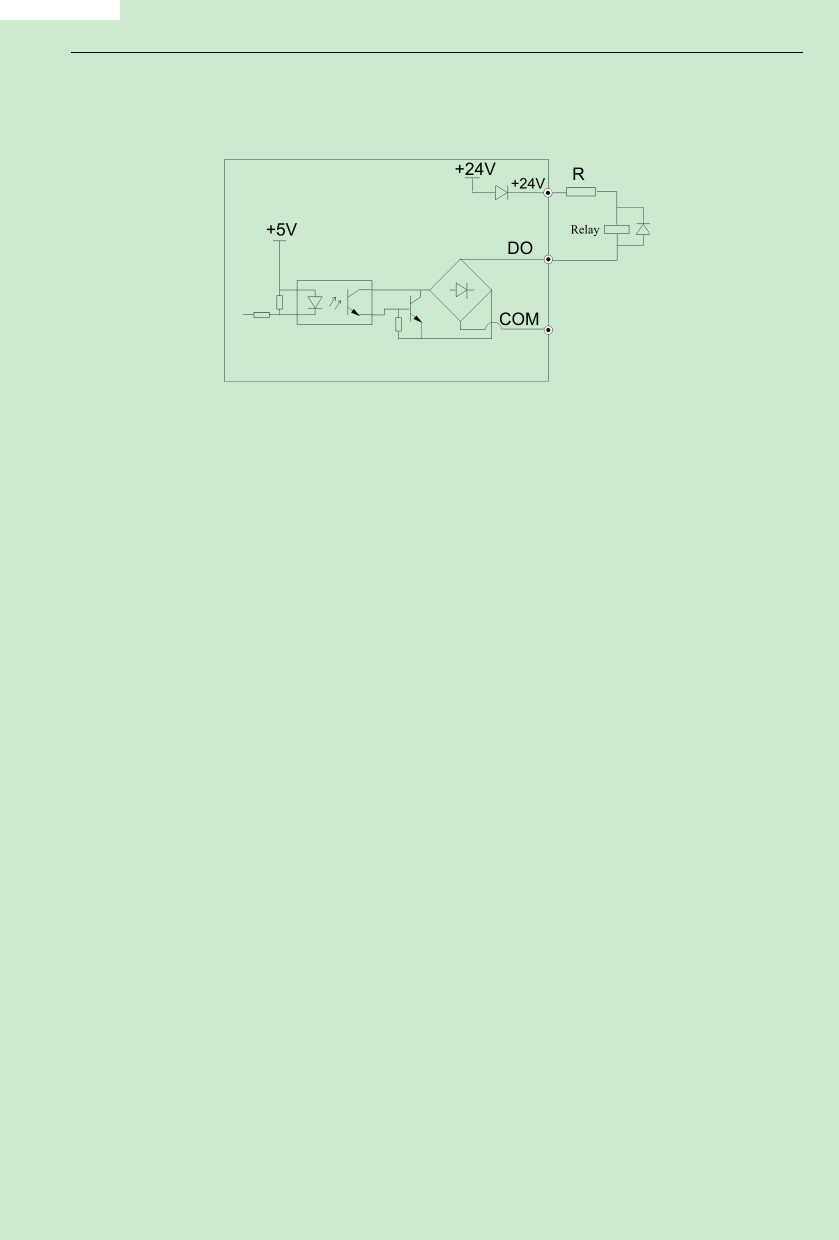
Otherwise, when the digital output terminal has output, the DC 24V power supply and output
circuit will be damaged immediately.
Fig.3-13 Schematic diagram for connection of digital output terminal
(5)Delay output terminal RA/B/C、TA/B/C wiring
If driving an inductive load(such as the electromagnetic relay,the contactor), surgevoltage
absorption circuit should be installed, such as RC absorption circuit(Pay attention that its leaking
current should be less than keeper current of the contactor or relay controlled by it),
voltage-sensible resistance, and diode,etc.(If it is used in DC electromagnetic loop, check the
polarity when install). Component of absorption circuit should be installed on the two side of the
coil of delay or contactor.
3.6 EMC Issues
3.6.1 Influence ofHarmonics
1) The high frequency harmonics of mains supply will influence the rectifying circuit of the
inverter. The harmonics will heat the rectifying circuit and even damage the circuit. So, it is
recommended to install the filtering device in the environmentwhere the power quality is poor.
2)Since the inverter output has high frequency harmonics, the output cannot be installedwith
capacitor or surge suppressing devices because the capacitor and surge suppressing device may
resonate the circuit and damage the equipment.
3.6.2 EMI
1) Two kinds of EMI, one is the EMI around the inverter and disturbs the inverter. This kind of
EMI is weak, besides the inverter has been designed with strong immunity.Another is the EMI
from the inverter that may influence the equipment around the inverter. The inverter itself is a
disturbance source because it outputs PWM wave through high carrier frequency, so solving the
- 30-
