ACD320user manual
Installation and wiring
When selecting the brake unit for the inverter above 18.5kW,pay attention that the polarity of
(DC+) and (DC-) cannot be reverse, otherwise the inverter may burn or be damaged.
The cable length of brake unit shall be less than 10 mand twisted pair cables shall be used.
Do not connect the brake resistor directly to the DC bus, otherwise the inverter may burn or be
damaged.
C. Brake resistor terminals of B1、B2(DC+)
The brake resistor terminal is effective only for the inverter of 15kW or below and has a built-in
brake unit. Select the recommended resistor with the cable length of less than 5m, otherwise the
inverter may burn or be damaged.
D. Inverter output U, V and W:
Inverter output terminals cannot connect to capacitors or surge snub devices, otherwise the
inverter may be in protective status or damaged.
If the cables between the motor and the inverter are too long, electrical resonance may occur due
to the distributed capacitance,whichmay result in damaging the motor insulation or big leakage
current, so if the cable length is longer than 100m,AC reactormust be installed.
E. Grounding Terminal :
GroundingTerminal must be connected to earth reliably and the grounding resistance shall be
less than 5Ω, otherwise the equipmentmay work abnormally or be damaged. Do not share the PE
and neutral line of themains supply.
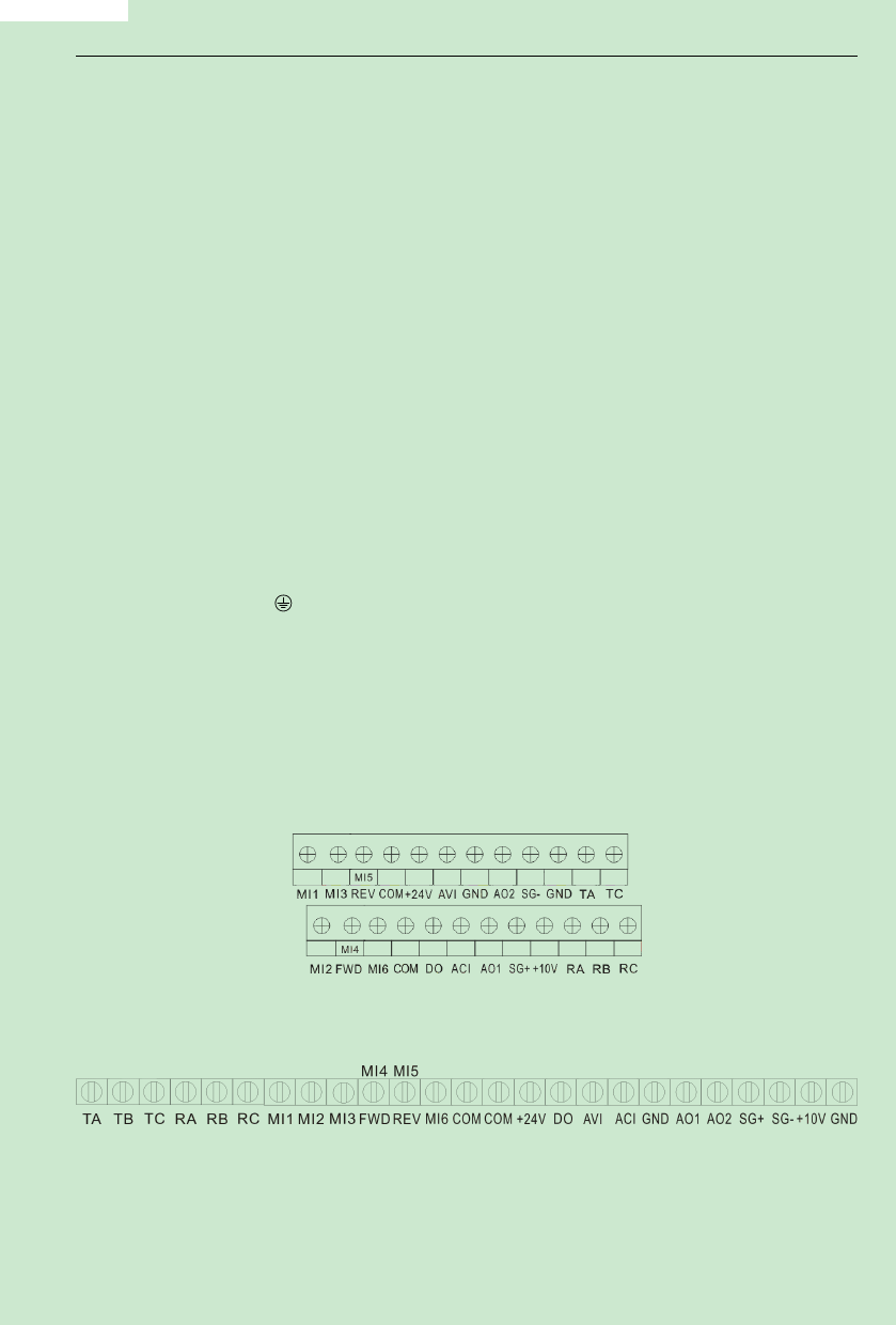
3. 5 Control Terminals and Wiring
1)Layout of ControlTerminals(Fig.3-4,Fig3-5):
Below 7.5KW
Above 11KW
Fig.3-4
Fig.3-5
- 24-

