9
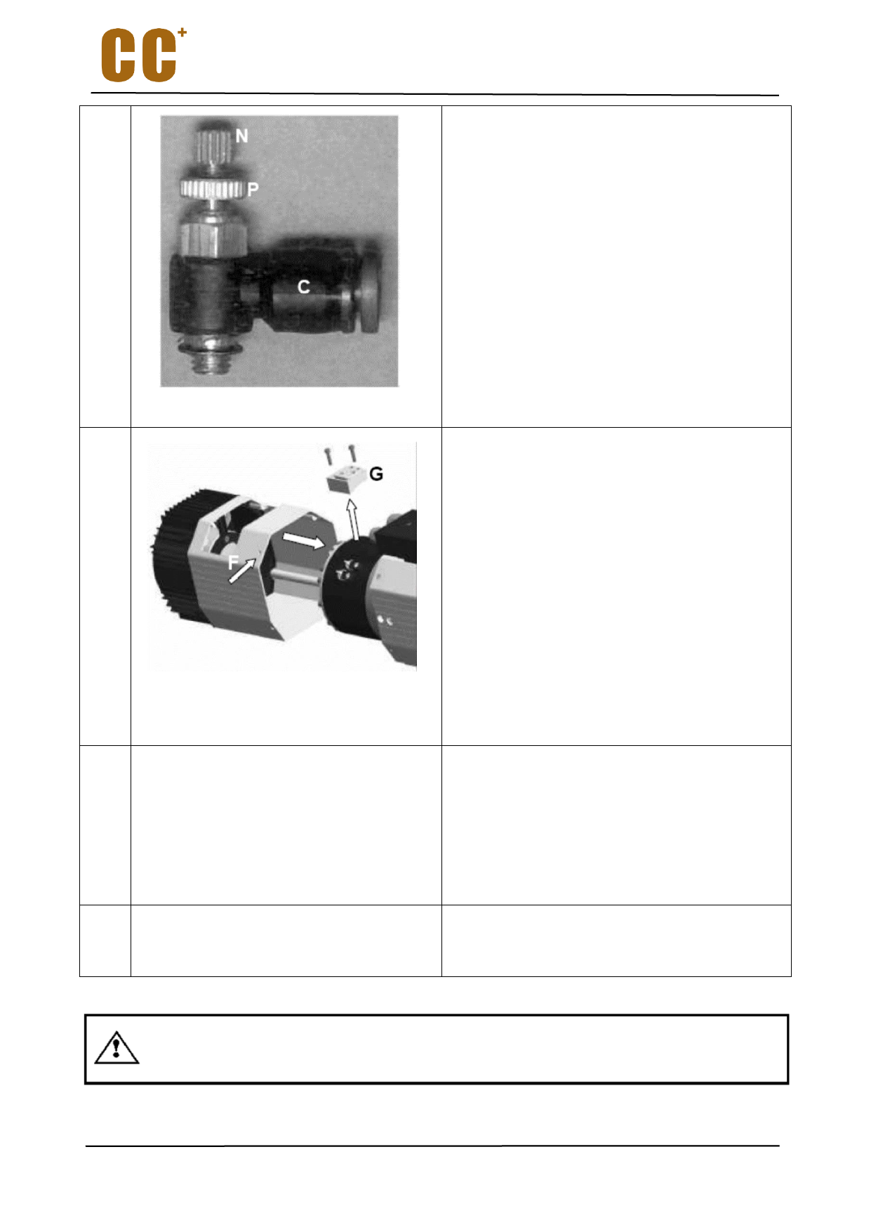
C. Quick connector with pressure regulator
N. Regulator
P. Lock nut
As shown in step 8, install a pressure gauge
M to measure the output pressure of C.
Connect E with 4 bar (58 PSI) air source.
Adjust the regulator N until the pressure
gauge is 0.8 bar (11.6 PSI).
Tighten the lock nut P to fix it.
Disconnect the pressure gauge M and hose
D and H from the connector C
10
Before installing the cooling fan cover, you
must remove the part G.
Remove two screws from the part G.
Take off the part G, take care not to lose or
damage the seal.
Install cooling fan cover and use screw F for
fixing
Install the part G, pay attention to the correct
installation of the seal, and then tighten the
two screws.
Connect hose A and B to the quick connector
D and C (see Step 4 of the schematic).
Connect the electrical connector of the
cooling fan.
11
In accordance with the instructions in section
10.2.3:
Remove the sensor from the cylinder;
Fit it on the new cylinder;
Calibrate sensor;
Close sensor chamber.
12
Use a M6 hexagon angle wrench to remove the
external compressed air connector from the old
cylinder and install it on the new cylinder.
After replacing the cylinder assembly, calibrate the sensors.
43

