GENERAL INSPECTION AFTER INSTALLATION
CHECK THE ELECTROSPINDLE BEFORE START UP
Positioning
There should be at least 100 mm space behind the cooling fan cover.
Pneumatic connection
Check the correctness of the pneumatic connections, the pressure levels used and the purity of the
compressed air.
With the spindle at standstill and the tool holder inserted, check there is a uniform, continuous outlet
of air from the area of the spindle nose around the shaft.
The air jet for cleaning the cone must be present during the tool change phase.
The pressurization air must always be present, even when the electrospindle is stopped.
The diameter of tube for tool change must be 8mm and the air pressure is 7bar (100psi); the diameter
of tube for pressurization and cleaning the cone must be 8mm and the air pressure is 4bar (58psi).
Tool release cylinder is single-acted electrical connection
Electrical connection
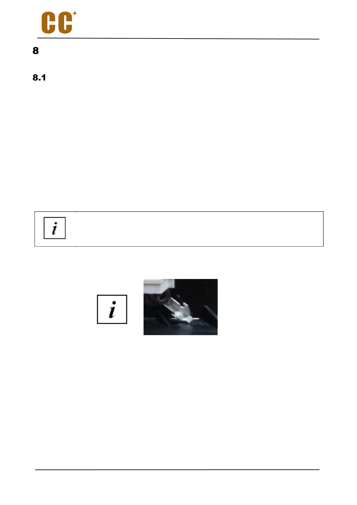
The earthing wire of the electrospindle must be connected to this (shown in the below fighure)
Inverter programming
The maximum voltage set on the inverter must correspond to the rated value indicated on the motor
rating plate;
The frequency value at which the maximum voltage (rated frequency) is to be attained must
correspond to the value indicated on the motor rating plate;
The maximum speed set on the inverter must correspond to the value indicated on the motor rating
plate;
The maximum direct current supplied to the inverter must correspond to the rated current indicated
on the motor rating plate;
If it is considered necessary to check the other parameters of the inverter, please contact CCMOTOR.
24
