LAYOUT FOR THE PNEUMATIC CIRCUIT
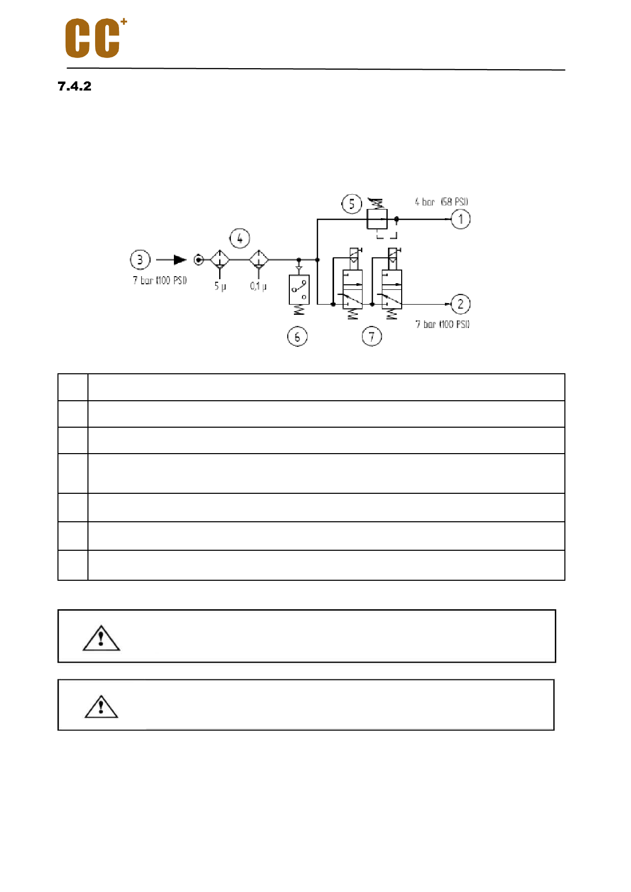
As shown in the bellowed figure, it is the pneumatic system circuit which must be arranged by the customer.
The use of two electric valves in series instead of just one reduces the possibility of malfunctioning.
Although such malfunctioning is very rare, it may cause serious results. Therefore the application of the
redundancy is suggested.
1 Cone cleaning and pressurization air inlet
2 The tool release air inlet
3 Factory air supply
4 Compressed air filtration and drying with automatic condensed water discharge: the first filter
5μm, the second filter 0.1μm
5 4 bar (58PSI) pressure regulator.
6 Pressure switch
7 A pair of two position three way solenoid valves
Two separate loops are used to connect the solenoid valve (position 7 in the figure)
to the control unit or the manual control system.
Important note: The air source in the pneumatic loop must be dry and
filtered.
When the machine is running, even if the electrospindle stops, the compressed air should be provided at
any time to prevent dust and dirt from entering the electrospindle.
When the electrospindle stops, make sure that there is a steady flow of air around the electrospindle.
Otherwise, check the pneumatic circuit and connection.
18

